

|
|
 |
 |
 |
|
|
Antentop is FREE e-magazine devoted to Antennas and Amateur Radio an
Special page devoted to
Jagadis Chandra Bose

Custom Search
|
ANTENTOP-
02- 2003, # 003 |
Jagadis Chandra Bose |
|||
|
|
||||
|
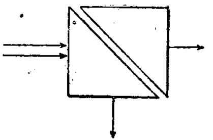
touch,
radiation propagates unhindered through both prisms. By introducing
a small air gap, the combination becomes avariable attenuator
to incident radiation; this is illustrated in Bose's original
diagram, shown in Figure 13. Bose investigated this prism attenuator
experimentally; his results were published in the Proceedings
of the Royal Society in November, 1897 [8]. Schaefer and Gross
[16] made a theoretical study of the prism combination in 1910;
the device has since been described in standard texts. At the National
Radio Astronomy Observatory in Tucson, Arizona a new multiple-feed
receiver, operating at a wavelength of 1.3 mm, has recently been
built and installed on the 12 Meter Telescope at Kitt Peak [17]. |
Figure 13. Bose's 1897 diagram of the double-prism
attenuator. |
|||
|
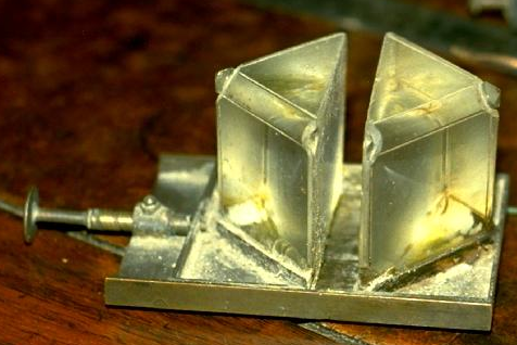
Figure 14. One of Bose's original double-prism
attenuators, with adjustable air gap. |
||||
|
The system
is an 8-feed receiver, where the local oscillator is injected
into the superconducting tunnel junction (SIS) mixers optically.
With an SIS mixer receiver the power level of the injected local
oscillator is critical; each of the 8 mixers requires independent
local oscillator power adjustment. This is achieved by adjustable
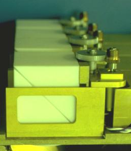
prism attenuators. Figure 15
shows 4 of these 8 prism attenuators, installed on one side of
the 8-feed system; this can be compared with Figure 14, which
is a photograph taken at the Bose Institute in Calcutta in 1985,
of an original prism system built by Bose. CONCLUSIONS Research into
the generation and detection of millimeter waves, and the properties
of substances at these wavelengths, was being undertaken in some
detail one hundred years ago, by J.C. Bose in Calcutta. Many of
the microwave components familiar today - waveguide, horn antennas,
polarizers, dielectric lenses and |
Figure 15. Four of the 8 double-prism attenuators
used to control local oscillator injection into the NRAO 1.3-mm
8-beam receiver in use at the 12 Meter Telescope at Kitt Peak.
|
|||
|
|
|
|||
|
|
Page 95 |
|||
 |
 |
 |
 |
Just for Fun:

Powered byIP2Location.com
Thanks for your time!
Last Updated:
March 8, 2020 13:16