


|
|
 |
 |
 |
|
|
Antentop is FREE e-magazine devoted to Antennas and Amateur Radio an
Special page devoted to
Jagadis Chandra Bose

Custom Search
|
ANTENTOP-
02- 2003, # 003 |
Jagadis Chandra Bose |
|
|
|
||
|
Oscillation is produced by sparking between 2 hollow hemispheres and
the interposed sphere. There is a bead of platinum on the inside
surface of each hemisphere. For some experiments, a lens of glass
or of sulphur was used to collimate the radiation - the first
waveguide-lens antenna. The lens was designed according to the
refractive index measured by Bose at the wavelength in use. Figure
3(b) shows Bose's drawing of such a radiator; the sparks
occur between the two outer spheres to the inner sphere, at the
focal point of the lens L at the right. Bose
was able to measure the wavelength of his radiation with a reflecting
diffraction grating made of metal strips [7]. Figure 4(a)
is a photograph of one of his radiating antennas; part
of the spark oscillations are generated inside the overmoded
circular waveguide. A polarizing grid is built into the antenna,
clearly visible at the radiating end of the waveguide. Figure
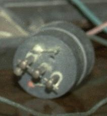
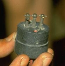
4(b) shows a closeup of the dual spark gaps used for the transmitter;
the sparks are generated between the 2 outer spheres and the inner
sphere. Figure 4(c) shows both a transmitting antenna (left) and
the receiver (right), with a dual prism in between set on the
experimental rotating table. |
Figure 3(b)
------------------------------------------------------------- Figure 3 Bose's diagrams of his radiators.
(a) shows the radiator used to generated
5-mm radiation, while (b) shows the arrangement with a lens L at the exit of the waveguide [2].
In some designs the mounting stems for the outer spheres could
be inclined to adjust the dimension of the spark gaps. |
|
|
Figure 4(a) One
of Bose's transmitter antennas (being held on the right of the
picture). Note the polarizing grid; the spark gap is just visible
behind the grid. In the background behind this antenna part of
the high voltage equipment used to generate the spark can be seen.
At the left of the picture is a receiving horn. |
||
|
|
||
|
|
|
|
|
Figure
4(b): A closeup of the spark
gaps normally mounted inside the transmitting antenna |
||
|
|
Page 90 |
|


 |
 |
 |
 |
Just for Fun:

Powered byIP2Location.com
Thanks for your time!
Last Updated:
February 8, 2018 22:33