
Antentop is FREE e-magazine devoted to Antennas and Amateur Radio an
Special page devoted to
The Inverted L Ham Antenna

Custom Search
|
ANTENTOP- 01- 2018 # 022 |
The Inverted L Ham Antenna |
|
|
|
|
|
|
In addition to matching the 50- Ohm line impedance
to the antenna input resistance this network also corrects for
reactance in the antenna and thereby affords easier loading to
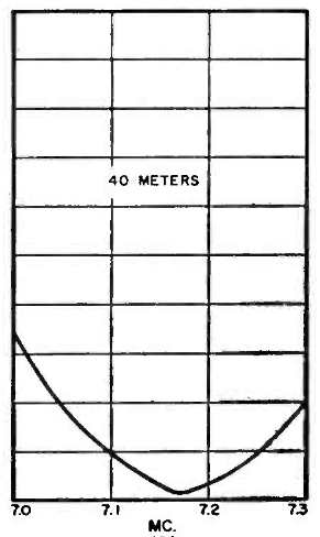
the transmitter. Figure 3
shows how the SWR varies over the band in the author's installation.
As can be seen, the lowest SWR was made to fall in the center
of the band because both CW and phone operation were to be used.
If the builder plans only CW or phone operation he may shift this
low SWR on 80 and 40 by making his adjustments on the frequency
to be used. In conclusion, it might be well to add that if you
are the band-hopping type of operator, remember that you will
have to visit the base of the antenna to switch bands. However,
even this small obstacle can be looked upon as a "blessing"
when you consider that in this age of automation most of us could
use a little exercise! Although this antenna cannot compete with a good beam,
it has proved to be the answer to a serious problem at W5LTD.
We have a sneaking suspicion that it will be in use for many years
to come since it has provided excellent contacts all over the
globe. We believe you will like it as well! 73! de Robert, W5LTD |
A |
|
|
B |
C |
|
|
Figure 3 SWR of the Antenna:
A- 80 meter, B- 40- meter, C- 20 meter |
||
|
|
|
|
|
Page- 21 |
||
 |
 |
|
 |
|
|
|||
Just for Fun:

Powered byIP2Location.com
Thanks for your time!
Last Updated:
January 2, 2020 21:26


