
Antentop is FREE e-magazine devoted to Antennas and Amateur Radio an
Special page devoted to
The Inverted L Ham Antenna

Custom Search
|
ANTENTOP- 01- 2018 # 022 |
The Inverted L Ham Antenna |
|
|
|
|
|
|
Figure 2 Complete schematic
diagram and parts list for the antenna matching unit |
||
|
|
|
|
|
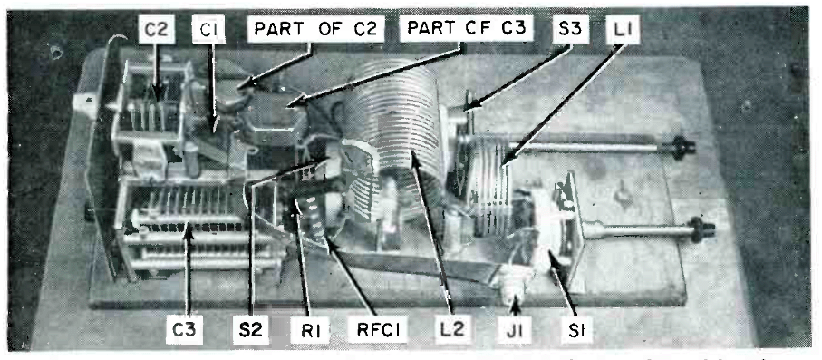
Photo 3 Photo showing the
construction on the network, which is built on a plywood board |
||
|
R1 and RFC were added to the circuit to bleed off any
static charge which might develop during thunderstorms. The knife
switch mounted on the utility pole is used to short the antenna
and protect the station equipment when the station is not on the
air during heavy electrical storms. This matching network has
handled a 400- W transmitter for a year and shows no signs of
heating or arcing of components. Calibration As mentioned earlier, it is not necessary for anyone
who plans to duplicate this antenna to do any design work to assure
a good impedance match. |
It is necessary, thought, to have a SWR in the line
while making the adjustments for low SWR on each band. Start your
adjustments with the switches set on the 20- meter band. While
watching the SWR indicator, rotate C1, until
the lowest reading is indicated. Small variables in the antenna installation may make
it necessary to change the taps on the coils one or two turns.
If this becomes necessary (it is if the SWR indicator cannot be
made to read a low value) the C1 setting should be re- adjusted
for a low reading after the taps are changed. When the SWR has
been made as low as possible on 20- meters the procedure is repeated
on 40 and 80 meters while adjusting C2 and C3 respectively. |
|
|
|
||
|
Page- 20 |
||
 |
 |
|
 |
|
|
|||
Just for Fun:

Powered byIP2Location.com
Thanks for your time!
Last Updated:
January 2, 2020 21:24


