
Antentop is FREE e-magazine devoted to Antennas and Amateur Radio an
Special page devoted to
The Inverted L Ham Antenna

Custom Search
|
ANTENTOP- 01- 2018 # 022 |
The Inverted L Ham Antenna |
|
|
|
|
|
|
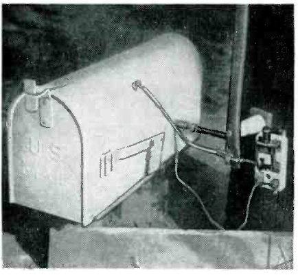
Photo 2 Matching network is inside rural mailbox at base of
antenna. Adjustments are accessible through door and back of mailbox.
Switch is for lighting protection The transmission line is buried about 6 inches in the
sod and runs from the house to the base of the antenna where it
enters the housing for the impedance matching networks. |
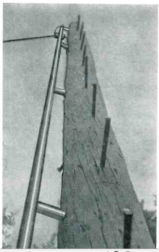
Photo 1 Vertical portion of antenna made of copper water tubing,
fastened by stand-off insulators |
|
|
The ground radials are made of four lengths of # 12
AWG copper wire 35 feet long. They stretch out in four directions
from the base of the pole and buried about six inches into the
turf. They are securely bonded together at pole to reduce losses
and are connected to the matching network by a copper braid. In
dry, sandy soil the radials should be made no less than 60 feet
long and their number increased to six. It is imperative that
the antenna have a good ground system, securely bonded to reduce
losses. The efficiency of this antenna on 80 meters is better
than that of the 33-foot and 44-foot verticals because the high
current (and high radiation) portion of the antenna has been raised.
Almost any length of wire or antenna configuration
can be made to look like 50 ohms or any other transmission line
impedance. This is the job of the impedance matching network.
Since an R.F. Bridge wasn't available, the impedance of the antenna
was measured with a Q- Meter and calibrated SWR Meter. The results
are given here as a matter of information only: 14.2 MHz., Z= 650-j100 Ohms; 7.2 MHz., Z
= 5000- j100 Ohms; 3.8 MHz., Z= 26 +
j0 Ohms. |
As can be seen from the circuit diagram of Figure 2
and the Photo
3, band-switching was handled by three separate switches.
If the builder substitutes a ganged switch and different parts
layout, it is suggested that the coils be placed at right angles
to each other to reduce mutual coupling. All components were mounted on a plywood board which
is slightly smaller than inside dimensions of the RFD- Type mailbox.
The finished unit is slipped into mailbox which provides excellent
protection from the weather. In the author's unit, C2 was made up to 50- pF unit
and 30- pF variable capacitor in parallel since the variable was
on hand. The actual capacity needed is 70- pF.
The 400- pF mica capacitor used as part of C3 should be of the
high current type. The one used here is a surplus Sangamo
Type A2LH (2500 Volts). The switches should also be able to withstand
high current if high power is to be used because they will carry
the full antenna current. The switches shown in the Photo
3 were taken from an army surplus antenna tuning unit. |
|
|
|
|
|
|
Page- 19 |
||
 |
 |
|
 |
|
|
|||
Just for Fun:

Powered byIP2Location.com
Thanks for your time!
Last Updated:
January 2, 2020 21:23


