

|
|
 |
 |
 |
|
|
Antentop is FREE e-magazine devoted to Antennas and Amateur Radio an
Special page devoted to
Old computer's PSU gives useful parts for antennas

Custom Search
|
ANTENTOP-
02- 2003, # 003 |
Old computer's PSU |
|
|
|
||
|
Conclusion: It is possible to use AT-33T transformer in design
of an RF ammeter. However, large dimensions of AT-33T transformer
and the limited frequency range of an RF ammeter made on its base
is the drawback of its application. If you want the RF ammeter to work
linearly on 160 - 30 meters use circuits given in Fig. 11-12. The drawback of these
circuits is that |
an expensive d.c. micro - ammeter of a 100μA full- scale deflection
is used there. If you need an RF ammeter for only one amateur range of 160, 80 or 40 meters, or you do not need linearity from your RF ammeter while this one is working on these ranges, use the circuit given in Fig. 7. In this case an inexpensive micro-ammeter with a 1000 micro Amper full- scale deflection will do well. |
|
|
|
||
|
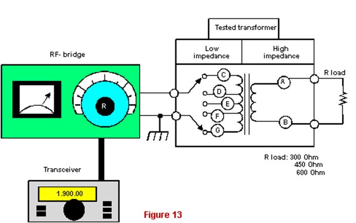
SUPPLEMENTARY Fig. 13 3 shows the measurement circuit for researches the opportunity. The primary |
winding (A - B in Fig. 3) was loaded to 300, 450, 600 Ohms. Using
different ways the secondary winding (C-
G in Fig. 13)
was connected to my home brew RF-bridge (this one was described
in the reference [1]). My transceiver K-116 fed the RF-bridge.
I made a lot of experiments and a lot of data for using of the ATX-33T
by way of an RF transformer were obtained. Most interesting data
will show below. |
|
|
Measurement circuit
|
||
|
Efficiency is the first However, what about an RF transformer has own input
resistance close to 50 Ohms, when it loaded to 300-600 Ohms? It
cannot serve as a final confirmation about its suitability for
transfer an RF energy. Any RF transformer
should have a good efficiency. Efficiency (Eff) is relation of
a power, which transformer's load is dissipated (P1),
to a power going from a transmitter to the transformer (P2).
We can write the formula as: Eff = P1/P2, Thus I took an important attention to measuring of the efficiency. I
used only one circuit (see Fig. 13)
for measurement of an input resistance, but I used three different
circuits for metering of the efficiency! Each of the circuits
gave own metering error, and demanded |
specific measuring
devices. I want to write about all of the three circuits, because,
they can be useful to hams who wants to do own
experiments with other types of PSU transformers. Fixing of the efficiency with the help
of RF- ammeters Fig. 14 shows very
obvious and simple circuit for "current" method of measurement
of the efficiency. Both RF currents, going to the transformer
and to the load, were metered. I metered the RF currents by self-made
RF ammeters (the RF ammeters were described in reference [1], pp. 21-22, 27- 31). When the RF currents
are fixed, it is possible to find the efficiency of the RF transformer.
The efficiency (Eff) is equal: Eff
= P1/P2, |
|
|
|
|
|
65 66 67 68 69 70 71 72 73 74 75 76 77
 |
 |
 |
 |
Just for Fun:

Powered byIP2Location.com
Thanks for your time!
Last Updated:
March 6, 2020 22:35