

|
|
 |
 |
 |
|
|
Antentop is FREE e-magazine devoted to Antennas and Amateur Radio an
Special page devoted to
Old computer's PSU gives useful parts for antennas

Custom Search
|
ANTENTOP-
02- 2003, # 003 |
Old computer's PSU |
|||
|
|
||||
|
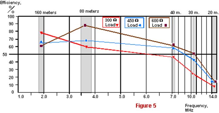
The efficiency vs.
frequency
|
||||
|
|
||||
|
On ranges of 160 -80 meters
it is possible to use the autotransformer only for a reception
mode with the transformer loaded to 450 or 600 Ohms and its primary
winding is connected to a 75-Ohm coaxial cable. On ranges of 160
-40 meters it is possible to use the autotransformer only for
a reception mode with the transformer loaded to 300 Ohms and its
primary winding is connected to a 50-Ohm coaxial cable. |
Note: Do not use the transformer without a load! It causes
a high VSWR and damage to the transformer. If the transformer
is used outside it should be protected against atmospheric influences.
It is possible to use an egg from a sweet surprise
"Chupa - Chups" for such a protection. |
|||
|
|
||||
|
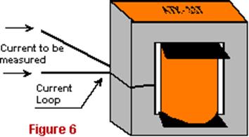
One more application - An RF ammeter I found one more useful application for AT-33T transformer.
This one was turned to a current transform for an RF ammeter. You need
to add only a current loop to AT-33T transformer and this one
will be a current transformer for an RF ammeter. The current loop
(or a current winding) contains only one turn of a wire placed
on a cheek of transformer's core (see Fig.
6). There was used a copper wire of 0.8 mm in diameter/#
20 AWG. |
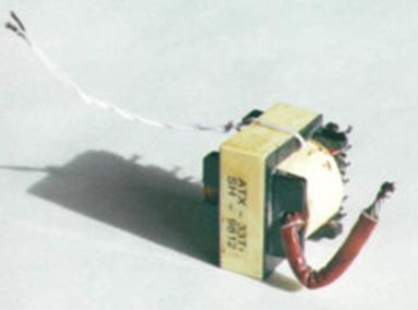
Current loop on the transformer side
|
|||
|
I found that the 24 volt winding (Fig. 7A)
as well as the inverter's winding (Fig. 7B) works as well as the meter's winding.
A germanium diode was used in an RF detector at the meter's winding.
A d.c. meter had a 1mA full scale deflection and 140-Ohm resistance.
To verify the work of the RF ammeter made on the base of AT-33T
transformer I connected it in serial with a control ammeter. Fig. 8 shows
the circuit. Note:
A control ammeter was a home brew RF ammeter designed by the reference
[1].
The RF ammeter was calibrated with the help of a
standard measuring equipment. Tab. 4 contains testing data for the RF ammeter shown in Fig. 8. Using
data from Tab.
4 I made diagrams "meter reading vs. frequency"
to the 24 volt winding and to the inverter's winding (see Fig. 9 ). The curve shows that the
inverter's winding (A- B) is the optimal winding for application in the
RF ammeter made on the base of AT-33T transformer. |
Current loop on the transformer side
|
|||
|
|
||||
|
|
Page 68 |
|||
65 66 67 68 69 70 71 72 73 74 75 76 77
 |
 |
 |
 |
Just for Fun:

Powered byIP2Location.com
Thanks for your time!
Last Updated:
March 8, 2020 21:29