

|
|
 |
 |
 |
|
|
Antentop is FREE e-magazine devoted to Antennas and Amateur Radio an
Special page devoted to
Old computer's PSU gives useful parts for antennas

Custom Search
|
ANTENTOP-
02- 2003, # 003 |
Old computer's PSU |
||||||||||||||||
|
|
|||||||||||||||||
| The RF ammeter has two drawbacks. Firstly, it works
on a limited frequency range, to 7 MHz for my test. Secondly, the
RF ammeter is too frequency dependent. I eliminated these defects
to a certain extent. A low- resistance resistor R1 bridged to the
meter's winding reduces the frequency dependence and extends the
frequency range. Fig. 10 shows the circuit
for the "linear" RF ammeter. A germanium diode was used
in the RF detector of the "linear" RF ammeter. A d.c.
meter had a 100μA full scale deflection and 320-Ohm resistance. |
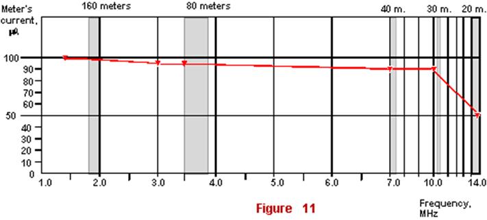
I picked up a value of the R1 that while at 1.5 MHz
the control RF ammeter showed the RF current of 0.1A the detector"s
meter had a full-scale deflection of 100μA. R1 had 110 Ohms
in this case. All other measurements were made at RF current of
0.1A and R1 of 110 Ohms. Data for the measurements are shown in
Tab. 5. Using data from this table I constructed
diagrams "meter reading vs. frequency" (see Fig. 11). |
||||||||||||||||
|
Table 5 Linear RF ammeter
Note: The RF current through a current loop is constant on
all frequencies and equals to 0.1A
|
|||||||||||||||||
| Fig.
11 shows that the
RF ammeter (Fig. 10) provides almost linear measurement of
the RF current on ranges of 160- 30 meters. It is possible to expand
the |
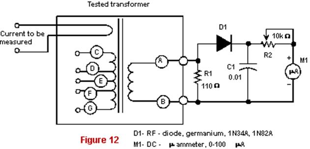
measuring range
of the RF ammeter with the help of a variable resistor connected
in serial with the d.c. meter. Fig.
12 shows such a RF ammeter with an expanded scale. |
||||||||||||||||
|
Meter reading vs. frequency
|
|||||||||||||||||
|
RF ammeter with an expanded scale
|
|||||||||||||||||
|
|
Page 71 |
||||||||||||||||
65 66 67 68 69 70 71 72 73 74 75 76 77
 |
 |
 |
 |
Just for Fun:

Powered byIP2Location.com
Thanks for your time!
Last Updated:
March 6, 2020 22:33