
 Some Model Quads:
My stock of models of quad beams having more than 2 elements is limited to a few published designs, mostly by K2OB and W6SAI. I have played a bit with the 3-element monoband quad design, but I do not claim to have optimized it fully.
Nevertheless, some of the modeled properties of published designs may be instructive in terms of setting expectations for what a modeling program is likely to say about a design. As with the remainder of the models in this set, the modeling program is NEC-4, but there are no differences in NEC-2 outputs for the same designs. Except where specifically noted, the designs use #14 AWG copper wire. All are 20-meter models, the band of choice for K2OB, whose designs make up half of those to be examined. As in past episodes, the primary operational properties that we shall graph include free space gain (in dBi), 180-degree front-to-back ratio (in dB), and SWR (referenced as relevant to a fixed value, such as 50 Ohms or 75 Ohms, or to the resonant impedance of the antenna in question).
The K2OB designs apparently have been optimized for maximum gain, which does not occur at the same frequency as maximum front-to-back ratio. The W6SAI 3-element design has intentionally reduced gain and striven for broad-band operation. My own 3-element model has striven for a balance among feedpoint impedance, gain, and front-to-back ratio.
Since comparisons with Yagi designs are inevitable, I have included a 5- element Yagi design to compare with the 5-element quads. The comparison, of course, is only at the level of modeling and cannot comment upon any perceived operational phenomena that have no correlates in modeling.
Throughout, I have discarded any references to wire-cutting formulas. In their place, I have list in tabular form the dimensions of the models themselves. As we shall discover, wire diameter does play a role in the performance curves of a quad beam. Hence, direct scaling must include wire diameter as well as loop length--or else adjustments will be required in the loop length if a certain wire size is retained. Likewise, changing wire size within any given model will require readjustment of loop sizes to return the curves to their original positions on the graphs or performance for gain, front-to-back ratio, and swr.
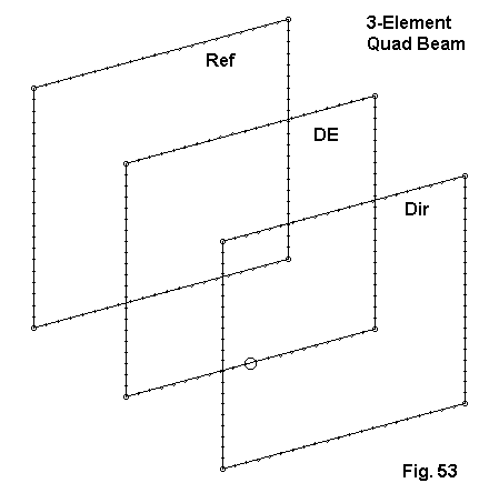
Fig. 53 provides an outline sketch of a typical monoband 3-element quad design. Essentially, only loop lengths and element spacing will change from design to design. Here is a table of the dimensions used in the models we shall compare.
          Reflector           Driver              Director
Model     Side L    Space     Side L    Space     Side L
           feet     Re-DE      feet     DE-Di      feet
K2OB324   18.006    11        17.562    13        17.426
3LQ2024   18.12     11        17.80     13        17.20
Orr2012   18.12     10        17.80     10        17.20
Note that my own design (3LQ2024) uses the same boom length (24') and element spacing (11' and 13') as the K2OB design, but different loop lengths. The W6SAI design uses the same loop lengths as mine, but on a shorter (20') boom with equal element spacing (10' each). The Orr design specifies #12 wire, while the other models use #14.
For reference, here are EZNEC model descriptions for each of the designs.
K2OB 3el quad 11/13=24                       Frequency = 14.175  MHz.

Wire Loss: Copper -- Resistivity = 1.74E-08 ohm-m, Rel. Perm. = 1

              --------------- WIRES ---------------

Wire Conn.--- End 1 (x,y,z : ft)  Conn.--- End 2 (x,y,z : ft)  Dia(in) Segs

1   W4E2  -9.003,  0.000, -9.003  W2E1   9.003,  0.000, -9.003    # 14   21
2   W1E2   9.003,  0.000, -9.003  W3E1   9.003,  0.000,  9.003    # 14   21
3   W2E2   9.003,  0.000,  9.003  W4E1  -9.003,  0.000,  9.003    # 14   21
4   W3E2  -9.003,  0.000,  9.003  W1E1  -9.003,  0.000, -9.003    # 14   21
5   W8E2  -8.781, 11.000, -8.781  W6E1   8.781, 11.000, -8.781    # 14   21
6   W5E2   8.781, 11.000, -8.781  W7E1   8.781, 11.000,  8.781    # 14   21
7   W6E2   8.781, 11.000,  8.781  W8E1  -8.781, 11.000,  8.781    # 14   21
8   W7E2  -8.781, 11.000,  8.781  W5E1  -8.781, 11.000, -8.781    # 14   21
9  W12E2  -8.713, 24.000, -8.713 W10E1   8.713, 24.000, -8.713    # 14   21
10  W9E2   8.713, 24.000, -8.713 W11E1   8.713, 24.000,  8.713    # 14   21
11 W10E2   8.713, 24.000,  8.713 W12E1  -8.713, 24.000,  8.713    # 14   21
12 W11E2  -8.713, 24.000,  8.713  W9E1  -8.713, 24.000, -8.713    # 14   21
               -------------- SOURCES --------------

Source    Wire      Wire #/Pct From End 1    Ampl.(V, A)  Phase(Deg.)  Type
          Seg.     Actual      (Specified)

1          11     5 / 50.00   (  5 / 50.00)      1.000       0.000       V

3el quad--Yagi Spacing--20m                  Frequency = 14.175  MHz.

Wire Loss: Copper -- Resistivity = 1.74E-08 ohm-m, Rel. Perm. = 1

              --------------- WIRES ---------------

Wire Conn.--- End 1 (x,y,z : ft)  Conn.--- End 2 (x,y,z : ft)  Dia(in) Segs

1   W4E2  -9.060,  0.000, -9.060  W2E1   9.060,  0.000, -9.060    # 14   21
2   W1E2   9.060,  0.000, -9.060  W3E1   9.060,  0.000,  9.060    # 14   21
3   W2E2   9.060,  0.000,  9.060  W4E1  -9.060,  0.000,  9.060    # 14   21
4   W3E2  -9.060,  0.000,  9.060  W1E1  -9.060,  0.000, -9.060    # 14   21
5   W8E2  -8.900, 11.000, -8.900  W6E1   8.900, 11.000, -8.900    # 14   21
6   W5E2   8.900, 11.000, -8.900  W7E1   8.900, 11.000,  8.900    # 14   21
7   W6E2   8.900, 11.000,  8.900  W8E1  -8.900, 11.000,  8.900    # 14   21
8   W7E2  -8.900, 11.000,  8.900  W5E1  -8.900, 11.000, -8.900    # 14   21
9  W12E2  -8.600, 24.000, -8.600 W10E1   8.600, 24.000, -8.600    # 14   21
10  W9E2   8.600, 24.000, -8.600 W11E1   8.600, 24.000,  8.600    # 14   21
11 W10E2   8.600, 24.000,  8.600 W12E1  -8.600, 24.000,  8.600    # 14   21
12 W11E2  -8.600, 24.000,  8.600  W9E1  -8.600, 24.000, -8.600    # 14   21

             -------------- SOURCES --------------

Source    Wire      Wire #/Pct From End 1    Ampl.(V, A)  Phase(Deg.)  Type
          Seg.     Actual      (Specified)

1          11     5 / 50.00   (  5 / 50.00)      1.000       0.000       V

Orr:  20 m: 3el                              Frequency = 14.175  MHz.

Wire Loss: Copper -- Resistivity = 1.74E-08 ohm-m, Rel. Perm. = 1

              --------------- WIRES ---------------

Wire Conn.--- End 1 (x,y,z : ft)  Conn.--- End 2 (x,y,z : ft)  Dia(in) Segs

1   W4E2  -9.060,  0.000, -9.060  W2E1   9.060,  0.000, -9.060    # 12   21
2   W1E2   9.060,  0.000, -9.060  W3E1   9.060,  0.000,  9.060    # 12   21
3   W2E2   9.060,  0.000,  9.060  W4E1  -9.060,  0.000,  9.060    # 12   21
4   W3E2  -9.060,  0.000,  9.060  W1E1  -9.060,  0.000, -9.060    # 12   21
5   W8E2  -8.900, 10.000, -8.900  W6E1   8.900, 10.000, -8.900    # 12   21
6   W5E2   8.900, 10.000, -8.900  W7E1   8.900, 10.000,  8.900    # 12   21
7   W6E2   8.900, 10.000,  8.900  W8E1  -8.900, 10.000,  8.900    # 12   21
8   W7E2  -8.900, 10.000,  8.900  W5E1  -8.900, 10.000, -8.900    # 12   21
9  W12E2  -8.600, 20.000, -8.600 W10E1   8.600, 20.000, -8.600    # 12   21
10  W9E2   8.600, 20.000, -8.600 W11E1   8.600, 20.000,  8.600    # 12   21
11 W10E2   8.600, 20.000,  8.600 W12E1  -8.600, 20.000,  8.600    # 12   21
12 W11E2  -8.600, 20.000,  8.600  W9E1  -8.600, 20.000, -8.600    # 12   21

               -------------- SOURCES --------------

Source    Wire      Wire #/Pct From End 1    Ampl.(V, A)  Phase(Deg.)  Type
          Seg.     Actual      (Specified)

1          11     5 / 50.00   (  5 / 50.00)      1.000       0.000       V
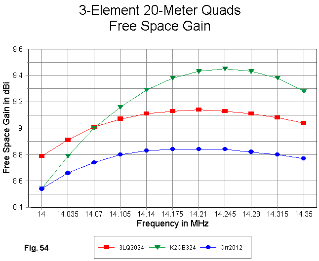
The gain curves across 20 meters for all three models appear in Fig. 54. The Orr and 3LQ designs show very parallel gain curves for their identical loop lengths. Hence, the gain difference is a measure of the shorter Orr boom and the different relative spacing of the elements.
The maximum gain for the K2OB model shows a peak at 14.245 MHz. The peak is roughly 0.3 dB higher than the gain of the 3LQ design at the same frequency--for the same boom length. However, the K2OB design shows a low-end fall-off. With judicious adjustment of the loop sizes, the gain curve might well be centered in the band so that it everywhere meets or exceeds the gain value of the 3LQ model on the same length boom.
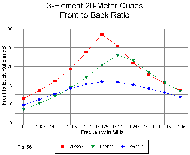
The Orr quad exhibits a very smooth front-to-back ratio curve in Fig. 55. However, values never reach the 20 dB mark. The K2OB design shows a peak above 25 dB, but the band-edge performance is poor, especially at the low end of the band. In conjunction with the gain curve, it appears that the antenna has been designed for the high end of 20 meters and the overall performance can be moved downward in frequency.
The 3LQ design on a 24' boom shows a much higher peak front-to-back ratio and a higher average value across the band than the other two designs. Nonetheless, band-edge performance is well below 15 dB, and the range for a front-to-back ratio in excess of 20 dB is only about 150 kHz of this 350 kHz band. It would appear that considerable sacrifice in forward gain performance may be necessary to achieve a relatively smooth front-to-back performance approach 20 dB at the band edges.
How much gain can be sacrificed and still have a quad advantage over a Yagi of similar boom length is a difficult question to answer. In my collection of models, I have K6STI 20-meter Yagi designs for 3-element Yagis on 24' booms and 4-element Yagis on 26' booms. The 3-element Yagi shows a mid-band free space gain of about 8.1 dBi, while the 4-element design shows a gain of 8.5 dBi. The peak Orr design gain just exceeds 8.8 dBi, so there is little margin with which to play to increase its front-to-back performance. Despite seeming differences in the gain of the K2OB and the 3LQ designs, when adjusted for a minimal front-to-back performance of 20 dB, the result would be identical designs. With the 3LQ version registering a peak gain just above 9.1 dBi, it shows about a full dB gain over the 3-element Yagi on the same length boom. It might require about half that advantage to yield a significantly better front-to-back performance.
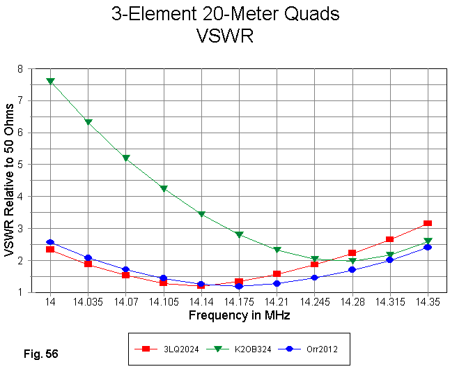
The SWR performance of the three designs relative to a 50-Ohm standard appears in Fig. 56. Neither the 3LQ nor the Orr design remains at under 2:1 SWR across 20 meters, although the Orr design comes closer to that goal. The K2OB design--intended for use with a matching circuit--shows the steepest curve of the 3 designs.
Antenna        Impedance at a Specified Frequency           Delta     Delta
          14.0           14.175         14.35                 R         X
K2OB      28.4 - j80.5   25.4 - j29.3   25.4 + j25.1         3.0      105.6
3lQ       34.4 - j37.4   42.4 + j 1.4   40.2 + j39.4         8.0       76.8
Orr       36.5 - j34.8   43.2 + j11.5   45.2 + j57.5         8.7       92.3
In all three models, the variation in the resistive component of the source impedance is small. We made a similar finding with respect to 2-element quads. Moreover, the pattern is variable, and as the 3LQ models shows, the peak resistive component may not occur at a band edge. However, the variation of reactance across the band is quite even and, comparatively speaking, very wide. Reducing this range to a more easily accommodated level is no small task indeed. At a basic design level, leaving the reduction to the masking effect of matching circuit losses or to cable losses is no solution at all, even if the process has practical advantages.

Since K2OB specifies the same dimensions for #16 through #12 AWG wire, #14 copper is used in the models. With the spacing already specified, we need tabulate only the loops sizes, expressed in terms of the length of each side, which are used for both versions of the antenna.
Reflector       Driver        Director 1     Director 2     Director 3
 17.786'        17.458'        17.356'        17.332'        17.332'
For reference, here is an EZNEC model description of the 80' boom model. To revise it for a 40' boom, make changes only to the Y-axis values for the directors.
5-el quad: K2OB 80'                            Frequency = 14.175  MHz.

Wire Loss: Copper -- Resistivity = 1.74E-08 ohm-m, Rel. Perm. = 1

              --------------- WIRES ---------------

Wire Conn.--- End 1 (x,y,z : ft)  Conn.--- End 2 (x,y,z : ft)  Dia(in) Segs

1   W4E2  -8.938,  0.000, -8.938  W2E1   8.938,  0.000, -8.938    # 14   21
2   W1E2   8.938,  0.000, -8.938  W3E1   8.938,  0.000,  8.938    # 14   21
3   W2E2   8.938,  0.000,  8.938  W4E1  -8.938,  0.000,  8.938    # 14   21
4   W3E2  -8.938,  0.000,  8.938  W1E1  -8.938,  0.000, -8.938    # 14   21
5   W8E2  -8.729, 10.000, -8.729  W6E1   8.729, 10.000, -8.729    # 14   21
6   W5E2   8.729, 10.000, -8.729  W7E1   8.729, 10.000,  8.729    # 14   21
7   W6E2   8.729, 10.000,  8.729  W8E1  -8.729, 10.000,  8.729    # 14   21
8   W7E2  -8.729, 10.000,  8.729  W5E1  -8.729, 10.000, -8.729    # 14   21
9  W12E2  -8.678, 33.300, -8.678 W10E1   8.678, 33.300, -8.678    # 14   21
10  W9E2   8.678, 33.300, -8.678 W11E1   8.678, 33.300,  8.678    # 14   21
11 W10E2   8.678, 33.300,  8.678 W12E1  -8.678, 33.300,  8.678    # 14   21
12 W11E2  -8.678, 33.300,  8.678  W9E1  -8.678, 33.300, -8.678    # 14   21
13 W16E2  -8.666, 56.600, -8.666 W14E1   8.666, 56.600, -8.666    # 14   21
14 W13E2   8.666, 56.600, -8.666 W15E1   8.666, 56.600,  8.666    # 14   21
15 W14E2   8.666, 56.600,  8.666 W16E1  -8.666, 56.600,  8.666    # 14   21
16 W15E2  -8.666, 56.600,  8.666 W13E1  -8.666, 56.600, -8.666    # 14   21
17 W20E2  -8.666, 79.900, -8.666 W18E1   8.666, 79.900, -8.666    # 14   21
18 W17E2   8.666, 79.900, -8.666 W19E1   8.666, 79.900,  8.666    # 14   21
19 W18E2   8.666, 79.900,  8.666 W20E1  -8.666, 79.900,  8.666    # 14   21
20 W19E2  -8.666, 79.900,  8.666 W17E1  -8.666, 79.900, -8.666    # 14   21

               -------------- SOURCES --------------

Source    Wire      Wire #/Pct From End 1    Ampl.(V, A)  Phase(Deg.)  Type
          Seg.     Actual      (Specified)

1          11     5 / 50.00   (  5 / 50.00)      1.000       0.000       V
The 5-element quad makes a fairly large model if we use plenty of segments per side to ensure convergence. However, it runs rapidly on a current generation computer (300 MHz or higher speed CPU).
Because the comparison will be inevitable, we might as well take it on from the beginning. How well does a 5-element quad model do against a 5-element Yagi model? Note that I have expressed the question in terms of modeled performance, not in terms of on-the-air performance. Since we shall restrict our inquiry to what NEC-4 modeling reports, we should not pretend that the answers are perfectly general.
The Yagi selected is a 5-element 45' boom model based on a design by W6NGZ. Further modeling studies of this and other long-boom 20-meter Yagis appears in another set of notes in this collection. (See Six Long-Boom Yagis.) The 45' boom length is the shortest of the collection and closest to the 40' K2OB model size. For reference, here is the model description of the W6NGZ Yagi.
5L45' W6NGZ CQ 10-96 p 22                      Frequency = 14.175  MHz.

Wire Loss: Aluminum -- Resistivity = 4E-08 ohm-m, Rel. Perm. = 1

              --------------- WIRES ---------------

Wire Conn.--- End 1 (x,y,z : in)  Conn.--- End 2 (x,y,z : in)  Dia(in) Segs

1        -215.60,  0.000,  0.000  W2E1 -156.00,  0.000,  0.000 6.25E-01   5
2   W1E2 -156.00,  0.000,  0.000  W3E1 -120.00,  0.000,  0.000 7.50E-01   3
3   W2E2 -120.00,  0.000,  0.000  W4E1 -72.000,  0.000,  0.000 8.75E-01   4
4   W3E2 -72.000,  0.000,  0.000  W5E1  72.000,  0.000,  0.000 1.00E+00  13
5   W4E2  72.000,  0.000,  0.000  W6E1 120.000,  0.000,  0.000 8.75E-01   4
6   W5E2 120.000,  0.000,  0.000  W7E1 156.000,  0.000,  0.000 7.50E-01   3
7   W6E2 156.000,  0.000,  0.000       215.605,  0.000,  0.000 6.25E-01   5
8        -205.95, 79.800,  0.000  W9E1 -156.00, 79.800,  0.000 6.25E-01   4
9   W8E2 -156.00, 79.800,  0.000 W10E1 -120.00, 79.800,  0.000 7.50E-01   3
10  W9E2 -120.00, 79.800,  0.000 W11E1 -72.000, 79.800,  0.000 8.75E-01   4
11 W10E2 -72.000, 79.800,  0.000 W12E1  72.000, 79.800,  0.000 1.00E+00  13
12 W11E2  72.000, 79.800,  0.000 W13E1 120.000, 79.800,  0.000 8.75E-01   4
13 W12E2 120.000, 79.800,  0.000 W14E1 156.000, 79.800,  0.000 7.50E-01   3
14 W13E2 156.000, 79.800,  0.000       205.950, 79.800,  0.000 6.25E-01   4
15       -198.21,155.160,  0.000 W16E1 -156.00,155.160,  0.000 6.25E-01   4
16 W15E2 -156.00,155.160,  0.000 W17E1 -120.00,155.160,  0.000 7.50E-01   3
17 W16E2 -120.00,155.160,  0.000 W18E1 -72.000,155.160,  0.000 8.75E-01   4
18 W17E2 -72.000,155.160,  0.000 W19E1  72.000,155.160,  0.000 1.00E+00  13
19 W18E2  72.000,155.160,  0.000 W20E1 120.000,155.160,  0.000 8.75E-01   4
20 W19E2 120.000,155.160,  0.000 W21E1 156.000,155.160,  0.000 7.50E-01   3
21 W20E2 156.000,155.160,  0.000       198.209,155.160,  0.000 6.25E-01   4
22       -196.55,337.920,  0.000 W23E1 -156.00,337.920,  0.000 6.25E-01   3
23 W22E2 -156.00,337.920,  0.000 W24E1 -120.00,337.920,  0.000 7.50E-01   3
24 W23E2 -120.00,337.920,  0.000 W25E1 -72.000,337.920,  0.000 8.75E-01   4
25 W24E2 -72.000,337.920,  0.000 W26E1  72.000,337.920,  0.000 1.00E+00  13
26 W25E2  72.000,337.920,  0.000 W27E1 120.000,337.920,  0.000 8.75E-01   4
27 W26E2 120.000,337.920,  0.000 W28E1 156.000,337.920,  0.000 7.50E-01   3
28 W27E2 156.000,337.920,  0.000       196.548,337.920,  0.000 6.25E-01   3
29       -189.90,530.400,  0.000 W30E1 -156.00,530.400,  0.000 6.25E-01   3
30 W29E2 -156.00,530.400,  0.000 W31E1 -120.00,530.400,  0.000 7.50E-01   3
31 W30E2 -120.00,530.400,  0.000 W32E1 -72.000,530.400,  0.000 8.75E-01   4
32 W31E2 -72.000,530.400,  0.000 W33E1  72.000,530.400,  0.000 1.00E+00  13
33 W32E2  72.000,530.400,  0.000 W34E1 120.000,530.400,  0.000 8.75E-01   3
34 W33E2 120.000,530.400,  0.000 W35E1 156.000,530.400,  0.000 7.50E-01   3
35 W34E2 156.000,530.400,  0.000       189.900,530.400,  0.000 6.25E-01   4

              -------------- SOURCES --------------

Source    Wire      Wire #/Pct From End 1    Ampl.(V, A)  Phase(Deg.)  Type
          Seg.     Actual      (Specified)

1           7    11 / 50.00   ( 11 / 50.00)      1.000       0.000       I
The Yagi model uses an extensive element diameter taper schedule, resulting in many model wires. The segment lengths have been kept as equal as possible throughout the model. The material is aluminum in diameters ranging from 1" down to 0.625". All of the models, both quad and Yagi, are in free space, with gain values in dBi.

The gain curves in Fig. 58 show different design goals for the two antenna types. The Yagi has been optimized for roughly the same gain across the 20-meter band, while the quads have been designed to achieve maximum gain. The 80' boom model shows a maximum gain of about 12 dBi peak, but falls below the Yagi level at the low end of the band. The 40' version of the antenna peaks just above the Yagi level, but falls 2 dB below the Yagi at the low end of the band.
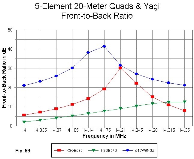
The modeled front-to-back performance of the quads is significantly below the level achieve by the Yagi anywhere within the 20-meter band, as demonstrated in Fig. 59. Although the 80' boom model peaks at 30 dB, the band-edge performance is below 10 dB. The low-level but rising curve of the 40' boom quad suggests that additional work needs to be done to optimize the model by bringing the front-to-back curve within the band.
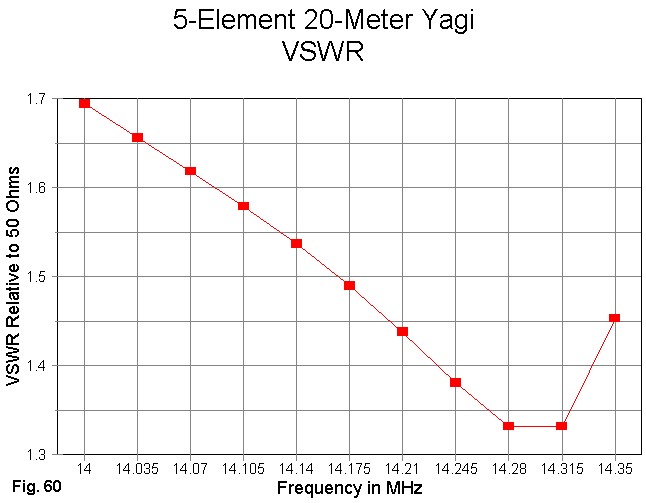
Only the 50-Ohm SWR curve for the Yagi is shown in Fig. 60. It achieves under 2:1 SWR across the entire 20-meter band. However, some of the other Yagi models in the long-boom collection achieve even better figures.
The quad-model source impedances are not amenable to graphing because of their wide variation, especially of the reactive component. The following table demonstrates the difficulty.
Antenna        Impedance at a Specified Frequency           Delta     Delta
          14.0           14.175         14.35                 R         X
80' quad  31.9 - j99.6   25.5 - j47.3   15.6 + j26.6        16.3      126.2
40' quad  25.6 - j98.0   35.2 - j52.7   26.6 - j20.0         9.6       78.0
45' Yagi  32.0 - j11.4   33.7 - j 2.3   35.9 - j 7.4         3.9        9.1
The ranges of both the resistive and reactive components of the Yagi source impedance are very small indeed, leading to a very stable matching situation. Likewise, the resistive components of the quad source impedances are also quite manageable. However, the quads exhibit (like their 3-element kin) wide swings of reactance across the 20-meter band, leading to very steep SWR curves, whatever the reference impedance value.
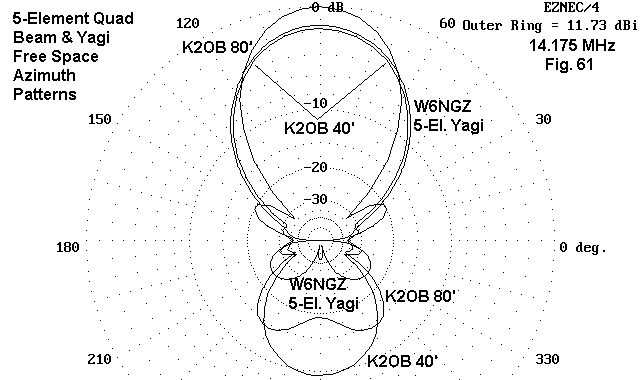
The relative performance at mid-band for the three antennas can be represented partially by overlaying free-space azimuth patterns, as done in Fig. 61. The superior gain of the 80' boom quad is clearly apparent, as is the relatively insignificant different in gain and horizontal beamwidth of the shorter quad and the Yagi. The Yagi's superior front-to-back performance is also clear.
One question bound to arise is why the quads do not exceed the Yagi by much greater margins, since they have been designed for maximum gain. Orr and Cowan, for example, give the quad loop a 1.4 dB advantage over a dipole--an advantage that should be reflected in the models, but is not. The answer to "why" is "wire."

Fig. 62 shows the free space gain of the two wire models. Of first note is the movement of the peak gain frequency by about 70 kHz, with the thinner wire showing the lower peak frequency. W4MB makes note in his book of the fact that for closed geometries, increasing the wire diameter also increases the resonant frequency of a loop. It also raises the frequency of peak gain for a multi-element quad. (We shall look into the gain differential in a moment.)
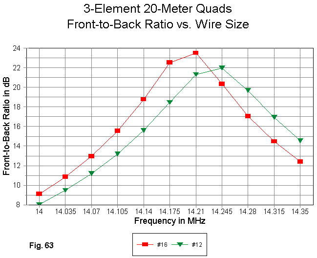
As Fig. 63 reveals, increasing the loop wire diameter also increases the frequency of peak front-to-back performance, in this case by about 35 kHz. In short, the operating center design frequency of the entire antenna is increased with each incremental increase in wire diameter.
Not only does the antenna operating frequency change with wire diameter, but as well the gain changes. More correctly expressed, the losses increase noticeably with a decrease in wire diameter. Whenever wire diameter makes a significant difference in performance parameters, we must also look at the difference made by the selection of materials for the elements, since the loss differential between, say, copper and aluminum may also make a difference in antenna performance.
To get a feel for what is involved, let's make a series of comparisons, first between 10-meter dipoles of radically different diameters. Despite the large difference in diameter, both size materials are used for different antennas. The test frequency is 28.5 MHz.
Diameter  Length    Material       Free Space     Source Impedance
 inches    feet                    Gain dBi       R +/- jX Ohms
 1        16.32     Zero-loss      2.13           71.7 - j 0.6
                    Copper         2.13           71.7 - j 0.5
                    Aluminum       2.13           71.7 - j 0.5

 0.0641   16.67     Zero-loss      2.14           71.9 - j 1.1
                    Copper         2.09           72.6 - j 0.4
                    Aluminum       2.05           73.0 - j 0.1
Operationally, the differences are not significant. However, here we want to notice trends. Once the wire diameter reaches a certain region--and 1" is within that region--the difference in efficiency among materials becomes insignificant. However, when the diameter is smaller, differences in material losses can become more readily apparent, as in the case of the #14 10-meter dipole. Not only does the gain vary, but as well the source impedance varies to reflect the added losses in less conductive materials.
Typically, HF quads are constructed of wire, which has a small diameter that shows the effects of material losses. Here is the same data for a single 10-meter quad loop for the three materials.
Diameter  Length    Material       Free Space     Source Impedance
 inches    feet                    Gain dBi       R +/- jX Ohms
 0.0641    9.13     Zero-loss      3.30           125.3 - j 0.7
           per      Copper         3.24           127.0 + j 0.8
           side     Aluminum       3.22           127.8 + j 1.5
For equal diameters and materials, the gain difference between a square quad loop and a dipole, when both are resonant, is about 1.15 dB in NEC model reckoning. However, the wire loop loses another increment of gain advantage when it competes with a 1" diameter dipole, even if the quad wire is copper and the dipole is aluminum. In multi-element arrays, these small increments add up quickly.
Let's do another comparison, this time between models of a 3-element quad beam and a 3-element Yagi. The quad is #14 AWG copper wire, while the Yagi is 1" aluminum. These models happen to be 14.175 MHz versions.
Antenna        Material       Free Space     F-B       Source Impedance
                              Gain dBi       dB        R +/- jX Ohms
3-el. Yagi     Zero-loss      8.14           27.5       25.6 - j 1.1
               Copper         8.12           27.4       25.7 - j 1.0
               Aluminum       8.11           27.3       25.7 - j 0.9
3-el. Quad     Zero-loss      9.49           25.3       40.3 + j 9.3
               Copper         9.13           28.5       43.2 + j11.5
               Aluminum       8.95           30.3       44.6 + j12.6
The gain change for the wire quad throughout the span of materials from lossless wire to aluminum is 18 times that of the 1" Yagi. Likewise, the other performance parameters in the wire quad change by significantly greater amounts as the materials are changed.
The upshot of these modeling comparisons is very basic: as long as quads (or other arrays) use thin wire with real losses, their performance will not achieve the theoretical maximum possible for any given design. In contrast, antennas using elements of appreciable diameter will tend to more closely approach theoretically achievable results, even with materials as lossy as aluminum. The differences between thin and fat wire versions of the same antenna can be significant.
Consider the 3-element quad array designated 3LQ2024, a 20-meter 3-element quad using #14 AWG copper wire. Now let us increase only the diameter of the driven element to 0.5" while leaving it copper. This effective diameter might be simulated by using a double wire driver with a spacing between wires of 1" or more. To reresonate the antenna requires an increase in the driver length per side of about 0.1 foot. For reference, here is the model description.
3el quad--Yagi Spacing--20m                  Frequency = 14.175  MHz.

Wire Loss: Copper -- Resistivity = 1.74E-08 ohm-m, Rel. Perm. = 1

              --------------- WIRES ---------------

Wire Conn.--- End 1 (x,y,z : ft)  Conn.--- End 2 (x,y,z : ft)  Dia(in) Segs

1   W4E2  -9.060,  0.000, -9.060  W2E1   9.060,  0.000, -9.060    # 14   21
2   W1E2   9.060,  0.000, -9.060  W3E1   9.060,  0.000,  9.060    # 14   21
3   W2E2   9.060,  0.000,  9.060  W4E1  -9.060,  0.000,  9.060    # 14   21
4   W3E2  -9.060,  0.000,  9.060  W1E1  -9.060,  0.000, -9.060    # 14   21
5   W8E2  -8.950, 11.000, -8.950  W6E1   8.950, 11.000, -8.950 5.00E-01  21
6   W5E2   8.950, 11.000, -8.950  W7E1   8.950, 11.000,  8.950 5.00E-01  21
7   W6E2   8.950, 11.000,  8.950  W8E1  -8.950, 11.000,  8.950 5.00E-01  21
8   W7E2  -8.950, 11.000,  8.950  W5E1  -8.950, 11.000, -8.950 5.00E-01  21
9  W12E2  -8.600, 24.000, -8.600 W10E1   8.600, 24.000, -8.600    # 14   21
10  W9E2   8.600, 24.000, -8.600 W11E1   8.600, 24.000,  8.600    # 14   21
11 W10E2   8.600, 24.000,  8.600 W12E1  -8.600, 24.000,  8.600    # 14   21
12 W11E2  -8.600, 24.000,  8.600  W9E1  -8.600, 24.000, -8.600    # 14   21

              -------------- SOURCES --------------

Source    Wire      Wire #/Pct From End 1    Ampl.(V, A)  Phase(Deg.)  Type
          Seg.     Actual      (Specified)

1          11     5 / 50.00   (  5 / 50.00)      1.000       0.000       V
Let's see how the models compare. The #14 wire model is designated 3LQ2024 and the 0.5" model is labeled 3LQ20245.
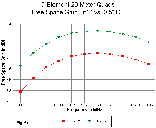
Fig. 64 compares the gain curves for the two models, which are identical except for the driver wire diameter and the small adjustment in length to recenter the curves. The difference is about 0.25 dB. The amount may not be operationally significant, but it is illustrative of the advantage of larger diameter elements.

In Fig. 65, we see that the front-to-back performance of the antennas does not change with the change in driver diameter. However, if the reflector and the director on this model were also increased in diameter, then all of the elements would have to be reoptimized to place the performance curves in the same relative positions in the 20-meter band.

The 50-Ohm SWR curves in Fig. 66 show a further advantage of the large diameter driven element. The SWR curve for the 0.5" driver model is flatter by far than that of the thin-wire model. Although the curve does not cover all of 20 meters with an SWR below 2:1, the improvement over the thin-wire version of the antenna is apparent, despite the fact that the fat driver shows a lower resonant source impedance (about 41 Ohms).
The purpose of these comparisons is not to promote any changes in quad construction. Rather, it is to explain why and to what degree wire diameter and material play a role in quad design and performance potential, as reported by NEC-4 models. Understanding what limits the performance of an antenna type may be as important as understanding what makes it work as well as it does.
This foray into larger monoband quad models is necessarily incomplete. We have looked at very few samples, and those samples show only a couple of the many design biases one might use in developing a large quad array. Nevertheless, the exercise may be accounted useful if we have acquired an appreciation for both the potentials and the limitations of this class of large parasitic antenna.
Updated 2-26-99. © L. B. Cebik, W4RNL. Data may be used for personal
purposes, but may not be reproduced for publication in print or any other medium
without permission of the author.
![]() Go to Further Notes on 3-Element Quads
Go to Further Notes on 3-Element Quads