
 Some Model Quads:
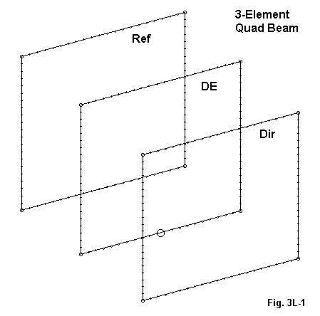
In the set of notes on multi-element monoband quads, we examined 3 different models of 3-element quad beams. The basic outlines of such a beam appear in Fig. 1.
The main difference among the quads was the boom length and spacing. For a refresher, here are the dimensions of the quads examined.
Model     Side L    Space     Side L    Space     Side L
           feet     Re-DE      feet     DE-Di      feet
K2OB324   18.006    11        17.562    13        17.426
3LQ2024   18.12     11        17.80     13        17.20
Orr2012   18.12     10        17.80     10        17.20
Note that my own design (3LQ2024) uses the same boom length (24') and element spacing (11' and 13') as the K2OB design, but different loop lengths. The W6SAI design uses the same loop lengths as mine, but on a shorter (20') boom with equal element spacing (10' each). The Orr design specifies #12 wire, while the other models use #14.
The Orr design exhibited the lowest gain on its short boom, while the K2OB design showed the highest peak gain--but only over a small operating bandwidth. Only the Orr design showed a feedpoint impedance close to 50 Ohms: the other two designs showed much lower impedances ranging from 25 to 40 Ohms. Interestingly, as the performance extracted from the quad increased at the design frequency, the operating and SWR bandwidths decreased.
There are some indicators of quad performance within these models that are worth pursuing a little further. So after we look at a 3-element Yagi as a comparator, we shall examine a 3-element quad that has been optimized beyond the limits set in the initial discussion.
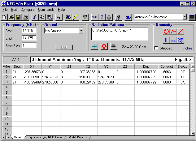
Ignore any dimension numbers past the third decimal place (or second), since everything is in inches. The excess specificity results from deriving the design from a set of simple equations, and eliminating the spurious decimal places from the spreadsheet calculations would be unproductive time.
In relationship to our upcoming quad examination, the SWR curve of the beam (relative to its design frequency resonant feedpoint impedance of 26.26 Ohms) is especially interesting.
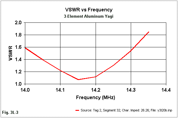
As shown in Fig. 3, the Yagi can be matched so as to operate over the entire 20-meter ham band with less than a 2:1 SWR ratio. How we arrive at this condition is shown partially by Fig. 4.
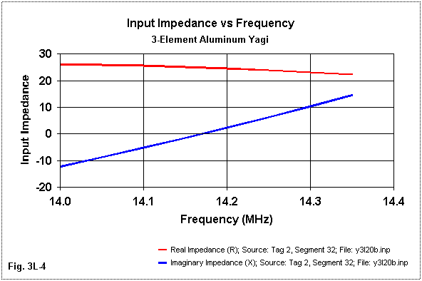
The total difference across the band in the resistive component of the feedpoint impedance is just over 4 Ohms. The reactance passes through a range of 26.3 Ohms. These are fairly small numbers when it comes to a bandwidth of nearly 2.5% of the center frequency.
The Yagi free-space gain shows a steady (nearly linear) increase across the band from 7.95 dBi at 14.0 MHz to 8.36 dBi at 14.35 MHz. The design maximizes the front-to-back ratio near the 14.175 MHz design frequency. The actual peak is about 28.2 dB just below the design frequency. At the risk of operating bandwidth, the resonant frequency and the front-to-back peak frequencies can be moved to other points within the passband for the antenna.
Although this design should be classified as a high-performance 3-element Yagi for its 22.5' boom and the number of elements, the general properties of the antenna are similar to those of other 3-element designs. They have come to form--rightly or not--the sorts of expectations we have of 3-element parasitic beams of all sorts, including quads.
On one level, we might argue that since only a model of a quad is at stake, the element size need not be realistic. We need not resort to such an argument, since this element diameter can be simulated with pairs of wires for each elements spaced a distance that yields for each of the loops the same overall resonant length. Most monoband quad frames can easily support 2 wires per spoke. In test models, there is negligible difference between the 2-wire simulation and the single fat element in terms of performance and efficiency. The numbers will not be absolutely identical, since the surface area of the two wires still does not equal the surface area of the single fat element. However, gain, front-to-back, and impedance numbers generally coincide to the first decimal place, as does the operating bandwidth of the resulting beam. Hence, the use of 1" elements in the design exercise is, in fact, practical--even if rarely used in actual quad building.
A second factor in the new design involves element spacing. Quad designs have long languished under two influences which have limited their performance. One is the desire for a near-50-Ohm feedpoint impedance. Effective design dictates that we let go of that goal and see what feedpoint impedance emerges if we optimize the other performance characteristics. Obviously, we can design so as to let the feedpoint impedance get too low. However, if a usable front-to-back ratio of about 20 dB is part of the design parameter set, then early indications are that a value in the mid-20s will emerge. This value, in fact, parallels the feedpoint impedance of good Yagi designs that also include a 20-dB front-to-back ratio requirement.
The other limiting factor is the traditional but non-rational urge to use a short boom and equal spacing between all elements. Although these design features have yielded quads with a convenient feedpoint impedance, the designs have not lived up to the so-called theoretical gain advantage of a quad over a similar Yagi of about 1.8 to 1.9 dB.
In redesigning the 3-element quad, one might start with new spacings at random and hope that some optimization program might catch a pair of magic distances. However, we need not resort to such measures, since we already have a large collection of parasitic beams with well-established element spacings for good performance. In fact, I took the Yagi we just described as the baseline for a fat-element quad. In the end, I enlarged the reflector-to-driver spacing by an inch and the overall boom length by 30 inches. This occurred in the process of determining the optimum loop circumference for each element in the beam.
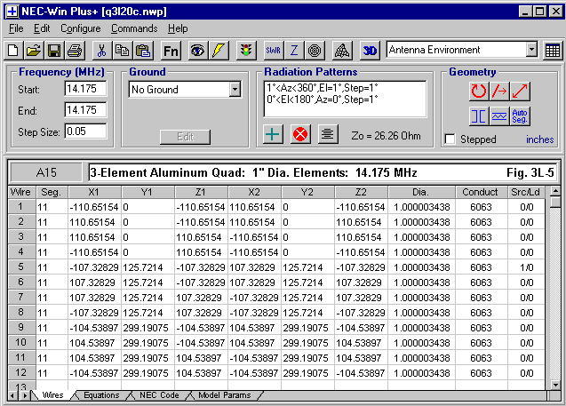
Once more, the design is equation driven, so the numbers in each dimension box are spreadsheet calculations, and not an attempt to be spuriously precise. Round them as you please. The real question is what I got for my pains.
At the design frequency of 14.175 MHz, the free-space gain is 9.97 dBi. This represents a gain of 1.84 dB over the Yagi. However, remember that the Yagi is 30" shorter than the 25' long quad. Nevertheless, the Yagi efficiency is about 99.5%, while the use of fat elements has raised to quad efficiency to 98.8%. The remaining difference owes to the fact that the quad elements are twice as long as those of the Yagi, and each increment of that extra length as a certain resistivity.
The 180-degree front-to-back ratio of the quad is just over 24 dB at the design frequency, with the quartering rear lobes yielding a worst-case value of 21.5 dB. The feedpoint impedance is just over 26 Ohms.
Despite these promising results, there are limitations to the design. Whoever first called a quad beam a wide-band device must have had only low-gain version in mind. As we saw in the K2OB designs, a quad optimized so far as possible to achieve its theoretic advantage over a Yagi has a narrower operating bandwidth, both in terms of SWR and in terms of performance specifications.
The present design is no exception. The VSWR curve, centered on the resonant impedance at the design frequency of 14.175 MHz, appears in Fig. 6.
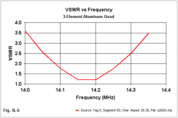
Why the curve is so steep becomes evident when we look at the resistance and reactance curves, shown in Fig. 7.
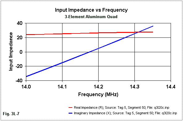
Although the resistive component varies by only 3.8 Ohms (similar to the Yagi variation of 4 Ohms), the reactance varies by over 70 Ohms (in contrast to the 26-Ohm variation of the Yagi). The result is a 2:1 VSWR bandwidth of only about 175 kHz within the 20-meter band. There is little that most matching systems can do to widen the operating bandwidth without introducing a set of losses. This design, at least (but in common with the K2OB design), suggests that a high gain quad may indeed be more narrow-banded than a comparable Yagi design of similar proportions.
Both the Yagi and the quad have well-behaved azimuth patterns, as shown in the overlay of Fig. 8.
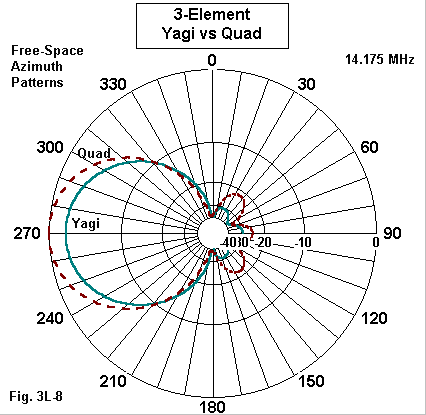
By well-behaved, I mean that neither design shows any incipient or real forward lobes other than the main lobe. Many VHF and interlaced HF Yagi designs show secondary forward lobes on each side of the main lobe, but these are absent in these two designs. Moreover the rear quadrants show only the usual set of three lobes.
The quad quartering rear lobes are larger than those of the Yagi. This fact suggests that further optimization of the quad design may be possible--perhaps through the use of a generalized optimization routine using both incremental and genetic techniques in combination. As I noted, the present design has been further optimized relative to those in the main discussion, but I did not say that it was finally or ultimately optimized.
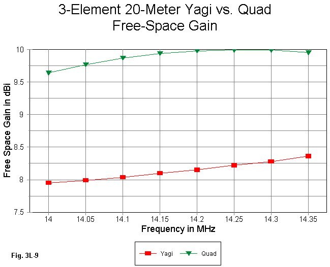
Fig. 9 compares the gain curves of the Yagi and the quad beams. As we noted earlier, the gain figures for the Yagi continues to increase nearly linearly across the band. However, the quad shows a distinct gain peak between 14.25 and 14.30 MHz. In most 3-element Yagi designs, it is not possible to combine peak front-to-back ratio values and peak gain values within a single HF ham band. However, the quad design (as well as the K2OB design in the main discussion) appears to make the in-band gain peak a more normal feature of a 3-element quad beam.
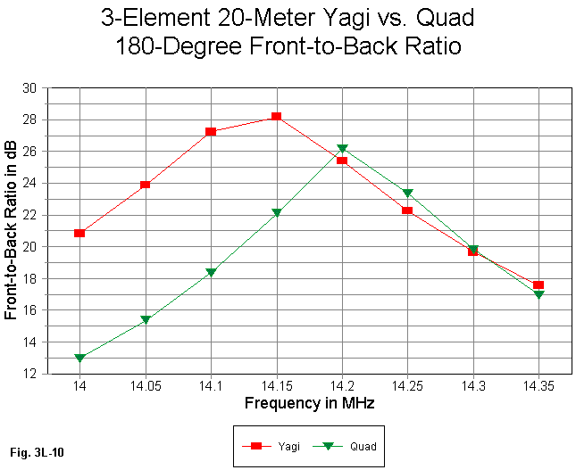
In Fig. 10, we can observe the 180-degree front-to-back curves for the two antenna types. The Yagi front-to-back peak occurs just below the design frequency. However, the quad peak is just above the design frequency. We have some freedom to move the front-to-back peak, but not unlimited freedom. If we move it too close to one or the other of the band edges, the operating bandwidth for either or both the gain and the feedpoint impedance can become very narrow--or we lose a significant part of the gain. (There are other antenna types--for example, the Moxon Rectangle-- where the SWR and the front-to-back curves are quite non-symmetrical, changing more rapidly on one side of the design frequency than the other. In such cases, we may intentionally choose a design frequency that will tend to provide as close as possible to equal values at the band edges instead of optimizing for a band-center frequency.)
Although the gain of the 3-element quad design is quite consistent across the band, the front-to-back values do not follow suit. The Yagi hits a low of 17.5 dB, while the quad shows a low of about 13 dB--at opposite ends of the band. In this connection, also note that the Yagi shows a decrease of feedpoint resistance with increasing frequency, but the quad shows an increase of feedpoint resistance as the frequency increases.
As a narrow-band beam, then, the 3-element quad approaches more closely than other designs I have so far seen the theoretical advantage over a comparable Yagi. (The Yagi still has better wide-band characteristics--and the Yagi design shown here is usually classified as a high-gain, narrow- band design.) The use of fat elements--real or simulated by multiple wires per element--and more typical parasitic element spacing produced a beam with higher efficiency and more gain, while retaining within its limited passband a good front-to-back ratio and a matchable feedpoint impedance.
However, the quad beam also revealed some ways in which its behavior is unlike that of a Yagi. The gain and resistance curves show distinctly non-Yagi behaviors. Moreover, designing a quad on the basis of Yagi parasitic element spacing yield an inherently narrow-band design.
It remains an open question whether or not it is possible to optimize a 3- element quad so that it exhibits high gain (for an antenna of its type) and broad bandwidth, while retaining the usual standard of a good front-to-back ratio (20 dB) and a usable feedpoint impedance (25 Ohms or more). Unless someone already has such a design in his/her pocket, it is likely that we shall not know until the 3-element quad has been run through optimizing routines as many times as Yagis have.
At most this note is a step in that direction. If it has done anything
useful, then perhaps it is to have elicited some of the further properties
of 3-element quads that may play a role in the "ultimate" design.