
 Some Model Quads:
My collection of larger (more than 2 elements) multi-band quads is fairly small, consisting of about 3.5 models. However, since one of them is of a 3.5 element 5-band quad, perhaps the score is even. Let's see how this works out.
First, I have modeled one of the multi-band quads from recent editions of the ARRL Antenna Book (page 2-12 in the 17th Edition). The antenna is a 4- element 3-band quad on a 40' boom. I count it as 1.5 models, since I have modeled is in both #14 and #12 AWG copper wire. The results, especially in light of my notes on wire size in monoband quads, are interesting.
Next, ON7NQ has shared a number of models with me in his efforts to improve the performance of a commercial 3-element 5-band quad on an 18' boom. One model of note simply adjusts the sizes of virtually all of the loops. A second model adds 2 new elements--new drivers for 10 and 12 meters--making approximately a 3.5 element quad--all on the same 18' boom.
In looking at these models, we should note a number of things. First and most obvious is the standard set of performance parameters that we have surveyed for all of the quads: free space gain in dBi, 180-degree front- to-back ratio in dB, and VSWR to some specified resistive impedance value. In addition to these matters, we may also wish to note how 3- and 4-element quads are similar to and differ from 2-element multi-band quads in various characteristics. Finally, we may also wish to record some factors related to boom length--at least so far as this small sample of models might suggest about the question.
As in all other cases, modeling has been done on NEC-4. The conventions of segmentation used in earlier multi-band quads are repeated here. For each side of a given quad loop, there are 7 segments on 10 meters, 9 segments on 12, 11 segments on 15, 13 segments on 17, and 15 segments on 20. Within practical limits, this scheme approaches the goal of having equal length segments throughout the model. Nonetheless, at least one model will have 724 segment distributed on 68 wires. Although NEC-2 will provide results as accurate as NEC-4 for these models, some implementations are limited to 500 segments and may prove less than fully adequate for the modeling task. MININEC results are also accurate if care is taken to ensure element length segment tapering at each corner of each loop. Without the use of symmetry or core enlargement, however, some of these models may be too large for some available versions of MININEC to handle.
As with past multi-band quads, only 20, 15, and 10 meters will undergo frequency sweeps. The 2 WARC bands (17 and 12) are so narrow that antenna performance characteristics do not significantly vary from their mid-band values. Each wide band will be divided into 10 equal segments. On 20, each segment is 0.35 MHz wide, on 15 each is 0.45 MHz wide, and on 10 each is 0.1 MHz wide. Hence, the graphs cover all of 20 and 10 meters and the first MHz of 10 meters.
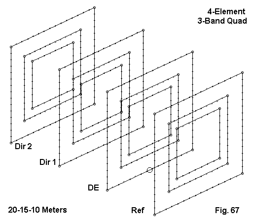
The following table lists the element lengths per loop side for each of the three bands.
Band      Reflector           Driver              Dir. 1             Dir. 2
          Side L    Space     Side L    Space     Side L    Space    Side L
           feet     Re-DE      feet     DE-D1      feet     D1-D2     feet
20        18.104    10        17.604    10        17.271    10       17.271
15        12.167    10        11.833    10        11.583    10       11.583
10         8.927    10         8.677    10         8.401    10        8.401
These loop lengths are very close to those used in one commercial quad using a shorter boom for a 3-element version. The change from band-to-band appears to be a matter of simple loop length scaling. The elements are shorter than the monoband loop lengths recommended in Orr and Cowan for 3- and 4-element quads. For reference, here is a model description.
arrl #14                                       Frequency = 14.175  MHz.

Wire Loss: Copper -- Resistivity = 1.74E-08 ohm-m, Rel. Perm. = 1

              --------------- WIRES ---------------

Wire Conn.--- End 1 (x,y,z : ft)  Conn.--- End 2 (x,y,z : ft)  Dia(in) Segs

1   W4E2  -4.200, 20.000, -4.200  W2E1   4.200, 20.000, -4.200    # 14    7
2   W1E2   4.200, 20.000, -4.200  W3E1   4.200, 20.000,  4.200    # 14    7
3   W2E2   4.200, 20.000,  4.200  W4E1  -4.200, 20.000,  4.200    # 14    7
4   W3E2  -4.200, 20.000,  4.200  W1E1  -4.200, 20.000, -4.200    # 14    7
5   W8E2  -4.200, 10.000, -4.200  W6E1   4.200, 10.000, -4.200    # 14    7
6   W5E2   4.200, 10.000, -4.200  W7E1   4.200, 10.000,  4.200    # 14    7
7   W6E2   4.200, 10.000,  4.200  W8E1  -4.200, 10.000,  4.200    # 14    7
8   W7E2  -4.200, 10.000,  4.200  W5E1  -4.200, 10.000, -4.200    # 14    7
9  W12E2  -4.339,  0.000, -4.339 W10E1   4.339,  0.000, -4.339    # 14    7
10  W9E2   4.339,  0.000, -4.339 W11E1   4.339,  0.000,  4.339    # 14    7
11 W10E2   4.339,  0.000,  4.339 W12E1  -4.339,  0.000,  4.339    # 14    7
12 W11E2  -4.339,  0.000,  4.339  W9E1  -4.339,  0.000, -4.339    # 14    7
13 W16E2  -4.464,-10.000, -4.464 W14E1   4.464,-10.000, -4.464    # 14    7
14 W13E2   4.464,-10.000, -4.464 W15E1   4.464,-10.000,  4.464    # 14    7
15 W14E2   4.464,-10.000,  4.464 W16E1  -4.464,-10.000,  4.464    # 14    7
16 W15E2  -4.464,-10.000,  4.464 W13E1  -4.464,-10.000, -4.464    # 14    7
17 W20E2  -5.792, 20.000, -5.792 W18E1   5.792, 20.000, -5.792    # 14   11
18 W17E2   5.792, 20.000, -5.792 W19E1   5.792, 20.000,  5.792    # 14   11
19 W18E2   5.792, 20.000,  5.792 W20E1  -5.792, 20.000,  5.792    # 14   11
20 W19E2  -5.792, 20.000,  5.792 W17E1  -5.792, 20.000, -5.792    # 14   11
21 W24E2  -5.792, 10.000, -5.792 W22E1   5.792, 10.000, -5.792    # 14   11
22 W21E2   5.792, 10.000, -5.792 W23E1   5.792, 10.000,  5.792    # 14   11
23 W22E2   5.792, 10.000,  5.792 W24E1  -5.792, 10.000,  5.792    # 14   11
24 W23E2  -5.792, 10.000,  5.792 W21E1  -5.792, 10.000, -5.792    # 14   11
25 W28E2  -5.917,  0.000, -5.917 W26E1   5.917,  0.000, -5.917    # 14   11
26 W25E2   5.917,  0.000, -5.917 W27E1   5.917,  0.000,  5.917    # 14   11
27 W26E2   5.917,  0.000,  5.917 W28E1  -5.917,  0.000,  5.917    # 14   11
28 W27E2  -5.917,  0.000,  5.917 W25E1  -5.917,  0.000, -5.917    # 14   11
29 W32E2  -6.083,-10.000, -6.083 W30E1   6.083,-10.000, -6.083    # 14   11
30 W29E2   6.083,-10.000, -6.083 W31E1   6.083,-10.000,  6.083    # 14   11
31 W30E2   6.083,-10.000,  6.083 W32E1  -6.083,-10.000,  6.083    # 14   11
32 W31E2  -6.083,-10.000,  6.083 W29E1  -6.083,-10.000, -6.083    # 14   11
33 W36E2  -8.635, 20.000, -8.635 W34E1   8.635, 20.000, -8.635    # 14   15
34 W33E2   8.635, 20.000, -8.635 W35E1   8.635, 20.000,  8.635    # 14   15
35 W34E2   8.635, 20.000,  8.635 W36E1  -8.635, 20.000,  8.635    # 14   15
36 W35E2  -8.635, 20.000,  8.635 W33E1  -8.635, 20.000, -8.635    # 14   15
37 W40E2  -8.635, 10.000, -8.635 W38E1   8.635, 10.000, -8.635    # 14   15
38 W37E2   8.635, 10.000, -8.635 W39E1   8.635, 10.000,  8.635    # 14   15
39 W38E2   8.635, 10.000,  8.635 W40E1  -8.635, 10.000,  8.635    # 14   15
40 W39E2  -8.635, 10.000,  8.635 W37E1  -8.635, 10.000, -8.635    # 14   15
41 W44E2  -8.802,  0.000, -8.802 W42E1   8.802,  0.000, -8.802    # 14   15
42 W41E2   8.802,  0.000, -8.802 W43E1   8.802,  0.000,  8.802    # 14   15
43 W42E2   8.802,  0.000,  8.802 W44E1  -8.802,  0.000,  8.802    # 14   15
44 W43E2  -8.802,  0.000,  8.802 W41E1  -8.802,  0.000, -8.802    # 14   15
45 W48E2  -9.052,-10.000, -9.052 W46E1   9.052,-10.000, -9.052    # 14   15
46 W45E2   9.052,-10.000, -9.052 W47E1   9.052,-10.000,  9.052    # 14   15
47 W46E2   9.052,-10.000,  9.052 W48E1  -9.052,-10.000,  9.052    # 14   15
48 W47E2  -9.052,-10.000,  9.052 W45E1  -9.052,-10.000, -9.052    # 14   15

             -------------- SOURCES --------------

Source    Wire      Wire #/Pct From End 1    Ampl.(V, A)  Phase(Deg.)  Type
          Seg.     Actual      (Specified)

1           8    41 / 50.00   ( 41 / 50.00)      1.000       0.000       V
The model has 48 wires and 528 segments. However, modeling time can be reduced by judicious use of the copy function for identical loops and by symbolic coordinate entries, if available. The source wires for each band are as follows: 20m = wire 41; 15m = wire 25; and 10m = wire 9. Source placement is at the wire center.
Because small changes in wire size resulted in noticeable differences in the antenna performance across the bands in question with monoband quads, I modeled this antenna using both #14 and #12 AWG copper wire. Only the #14 model is shown, since wire size is the only difference between the models.
As a handy reference, the following table lists the mid-band performance for each band of each version of the antenna.
Wire-     Freq.     Gain      F-B       Impedance
 Band      MHz      dBi       dB        R +/- jX Ohms
#14-20    14.175     9.60     20.8       40.8 + j 3.6
#12-20               9.74     22.0       38.0 + j 1.7
#14-15    21.225    10.10     16.8       87.6 + j 4.4
#12-15              10.16     15.9       85.3 + j 3.9
#14-10    28.5       8.93      8.3      105.0 - j35.0
#12-10               8.93      8.0      103.0 - j35.8
The differences in performance figures are almost completely insignificant. This fact suggests that element interaction among loops for the various bands may play a stronger role in determining performance characteristics in this 3-band model than modest changes in wire size. The closest loop set to an uninfluenced set is for 20 meters, and the differences in mid-band performance are greatest on that band. The performance curves across the bands bear out this suggestion.
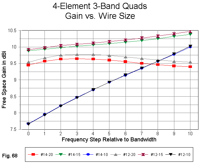
The gain curves in Fig. 68 show the virtual identity of the 10-meter gain for the two wire sizes. 15-meter gain does almost as well, and only 20-meter gain shows something interesting. The low-end increase in gain toward the peak value is slightly steeper for the fatter wire.
A rising gain curve across the band is natural for virtually any parasitic beam having a director and is the opposite trend from that shown by 2-element reflector-driver designs. However, the 10-meter curve strongly suggests that the performance for this band has not been optimized. The dimensions for 10-meters suggest that the design technique used to arrive at the dimension was simple scaling of the loop length from 20 and 15 meter. The result is, according to the model, relatively mediocre performance at the low end of 10 meters for a long-boom 4-element array.
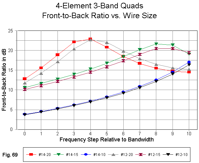
The front-to-back ratio curves in Fig. 69 tend to confirm that--if the model is reasonably accurate--inadequate attention has been paid to 10 meter dimensions. The front-to-back ratio on that band only rises above 10 dB at about 28.6 MHz and continues to climb toward the 29.0 MHz mark, where the scan ceased. In contrast, the front-to-back peaks for both 20 and 15 meters occur within the passband under study. In accord with the suggestion that the 20 meter loops are least affected by the other loops in the array--in other words, act most like a monoband array--the 20-meter front-to-back curves show a frequency displacement that is missing from the 15- and 10-meter curves.
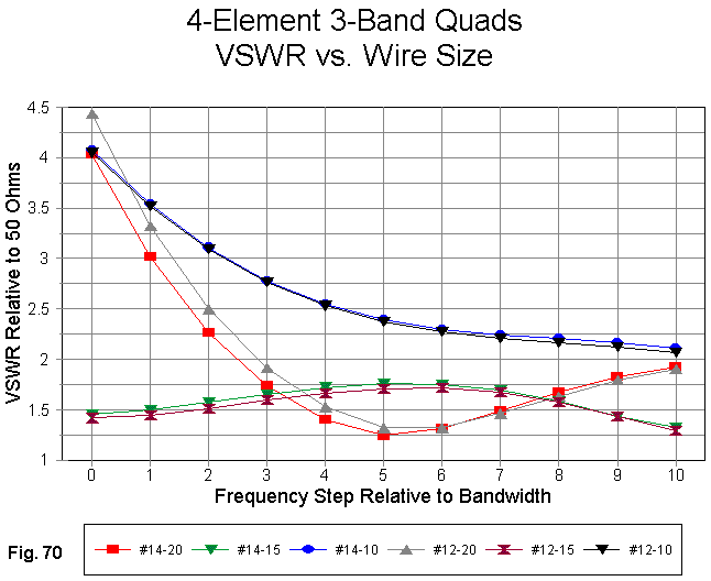
The VSWR curves in Fig. 70 are also revelatory. The 20-meter mid-band values suggested that the array might have a low SWR relative to 50 Ohms across that band. However, the curves show that SWR climbs precipitously below mid-band, as the resistive component of the source impedance approaches 20 Ohms. Although the mid-band impedance given for 15 meters suggests a better match to 75-Ohm line, the 50-Ohm SWR remains below 2:1 across that band. On 10 meters, the SWR only approaches 2:1 at 29 MHz. However, if the dimensions of all the 10 meter loops were changed to bring the performance reports within the pass band, it is likely that the 10-meter SWR would also decrease to a more acceptable set of values relative to 50 Ohms.
For reference, here is a table of source impedance values for each band, using the #14 model, recorded for the low, middle, and high points of each band.
Band           Impedance at a Specified Frequency           Delta    Delta
20 m      14.0           14.175         14.35                 R        X
          24.2 - j45.8   40.8 + j 3.6   67.7 + j34.5        43.5      80.3
15 m      21.0           21.225         21.45
          69.6 - j10.2   87.6 + j 4.4   60.7 + j11.3        26.9      21.5
10 m      28.0           28.5           29.0
          92.6 - j94.6   105.0- j35.0   104.9+ j 6.7        12.4     101.3
Above 29 MHz, the 10-meter impedance descends once more. It is likely that judicious loop alteration can bring the source impedance within a 2:1 50- Ohm SWR curve that occupies most of the first MHz of 10. Likewise, adjustment to the 20 meter driver length could also move its 2:1 SWR curve lower in the band. There is no reason to touch anything on 15, except perhaps to draw the front-to-back curve more symmetrically within the band.
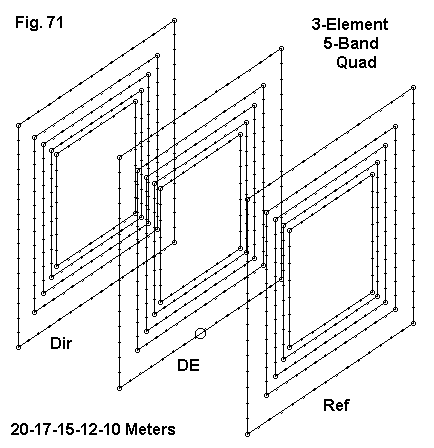
Since the sketch gives no hint of the final dimensions of this model (only one of several we discussed), the following table may help.
Band      Reflector           Driver              Dir. 1
          Side L    Space     Side L    Space     Side L
           feet     Re-DE      feet     DE-D1      feet
20        18.166    10        17.812     8        17.166
17        14.134    10        13.874     8        13.458
15        12.066    10        11.834     8        11.500
12        10.334    10        10.062     8         9.834
10         9.100    10         8.800     8         8.684
Compared to the dimensions given for the 3-band quad, 15 meters changes scarcely at all. In the case of both 20 and 10 meters, the loops have been enlarged, with the exception of the 20-meter director, which was decreased. The model for this 60-wire, 660 segment model follows.
ON7NQ 3 el 5 band #14                        Frequency = 14.175  MHz.

Wire Loss: Copper -- Resistivity = 1.74E-08 ohm-m, Rel. Perm. = 1

              --------------- WIRES ---------------

Wire Conn.--- End 1 (x,y,z : in)  Conn.--- End 2 (x,y,z : in)  Dia(in) Segs

1   W4E2 -52.100, 96.000,-52.100  W2E1  52.100, 96.000,-52.100    # 14    7
2   W1E2  52.100, 96.000,-52.100  W3E1  52.100, 96.000, 52.100    # 14    7
3   W2E2  52.100, 96.000, 52.100  W4E1 -52.100, 96.000, 52.100    # 14    7
4   W3E2 -52.100, 96.000, 52.100  W1E1 -52.100, 96.000,-52.100    # 14    7
5   W8E2 -52.800,  0.000,-52.800  W6E1  52.800,  0.000,-52.800    # 14    7
6   W5E2  52.800,  0.000,-52.800  W7E1  52.800,  0.000, 52.800    # 14    7
7   W6E2  52.800,  0.000, 52.800  W8E1 -52.800,  0.000, 52.800    # 14    7
8   W7E2 -52.800,  0.000, 52.800  W5E1 -52.800,  0.000,-52.800    # 14    7
9  W12E2 -54.600,-120.00,-54.600 W10E1  54.600,-120.00,-54.600    # 14    7
10  W9E2  54.600,-120.00,-54.600 W11E1  54.600,-120.00, 54.600    # 14    7
11 W10E2  54.600,-120.00, 54.600 W12E1 -54.600,-120.00, 54.600    # 14    7
12 W11E2 -54.600,-120.00, 54.600  W9E1 -54.600,-120.00,-54.600    # 14    7
13 W16E2 -59.000, 96.000,-59.000 W14E1  59.000, 96.000,-59.000    # 14    9
14 W13E2  59.000, 96.000,-59.000 W15E1  59.000, 96.000, 59.000    # 14    9
15 W14E2  59.000, 96.000, 59.000 W16E1 -59.000, 96.000, 59.000    # 14    9
16 W15E2 -59.000, 96.000, 59.000 W13E1 -59.000, 96.000,-59.000    # 14    9
17 W20E2 -60.375,  0.000,-60.375 W18E1  60.375,  0.000,-60.375    # 14    9
18 W17E2  60.375,  0.000,-60.375 W19E1  60.375,  0.000, 60.375    # 14    9
19 W18E2  60.375,  0.000, 60.375 W20E1 -60.375,  0.000, 60.375    # 14    9
20 W19E2 -60.375,  0.000, 60.375 W17E1 -60.375,  0.000,-60.375    # 14    9
21 W24E2 -62.000,-120.00,-62.000 W22E1  62.000,-120.00,-62.000    # 14    9
22 W21E2  62.000,-120.00,-62.000 W23E1  62.000,-120.00, 62.000    # 14    9
23 W22E2  62.000,-120.00, 62.000 W24E1 -62.000,-120.00, 62.000    # 14    9
24 W23E2 -62.000,-120.00, 62.000 W21E1 -62.000,-120.00,-62.000    # 14    9
25 W28E2 -69.000, 96.000,-69.000 W26E1  69.000, 96.000,-69.000    # 14   11
26 W25E2  69.000, 96.000,-69.000 W27E1  69.000, 96.000, 69.000    # 14   11
27 W26E2  69.000, 96.000, 69.000 W28E1 -69.000, 96.000, 69.000    # 14   11
28 W27E2 -69.000, 96.000, 69.000 W25E1 -69.000, 96.000,-69.000    # 14   11
29 W32E2 -71.000,  0.000,-71.000 W30E1  71.000,  0.000,-71.000    # 14   11
30 W29E2  71.000,  0.000,-71.000 W31E1  71.000,  0.000, 71.000    # 14   11
31 W30E2  71.000,  0.000, 71.000 W32E1 -71.000,  0.000, 71.000    # 14   11
32 W31E2 -71.000,  0.000, 71.000 W29E1 -71.000,  0.000,-71.000    # 14   11
33 W36E2 -72.400,-120.00,-72.400 W34E1  72.400,-120.00,-72.400    # 14   11
34 W33E2  72.400,-120.00,-72.400 W35E1  72.400,-120.00, 72.400    # 14   11
35 W34E2  72.400,-120.00, 72.400 W36E1 -72.400,-120.00, 72.400    # 14   11
36 W35E2 -72.400,-120.00, 72.400 W33E1 -72.400,-120.00,-72.400    # 14   11
37 W40E2 -80.750, 96.000,-80.750 W38E1  80.750, 96.000,-80.750    # 14   13
38 W37E2  80.750, 96.000,-80.750 W39E1  80.750, 96.000, 80.750    # 14   13
39 W38E2  80.750, 96.000, 80.750 W40E1 -80.750, 96.000, 80.750    # 14   13
40 W39E2 -80.750, 96.000, 80.750 W37E1 -80.750, 96.000,-80.750    # 14   13
41 W44E2 -83.250,  0.000,-83.250 W42E1  83.250,  0.000,-83.250    # 14   13
42 W41E2  83.250,  0.000,-83.250 W43E1  83.250,  0.000, 83.250    # 14   13
43 W42E2  83.250,  0.000, 83.250 W44E1 -83.250,  0.000, 83.250    # 14   13
44 W43E2 -83.250,  0.000, 83.250 W41E1 -83.250,  0.000,-83.250    # 14   13
45 W48E2 -84.805,-120.00,-84.805 W46E1  84.805,-120.00,-84.805    # 14   13
46 W45E2  84.805,-120.00,-84.805 W47E1  84.805,-120.00, 84.805    # 14   13
47 W46E2  84.805,-120.00, 84.805 W48E1 -84.805,-120.00, 84.805    # 14   13
48 W47E2 -84.805,-120.00, 84.805 W45E1 -84.805,-120.00,-84.805    # 14   13
49 W52E2 -103.00, 96.000,-103.00 W50E1 103.000, 96.000,-103.00    # 14   15
50 W49E2 103.000, 96.000,-103.00 W51E1 103.000, 96.000,103.000    # 14   15
51 W50E2 103.000, 96.000,103.000 W52E1 -103.00, 96.000,103.000    # 14   15
52 W51E2 -103.00, 96.000,103.000 W49E1 -103.00, 96.000,-103.00    # 14   15
53 W56E2 -106.87,  0.000,-106.87 W54E1 106.870,  0.000,-106.87    # 14   15
54 W53E2 106.870,  0.000,-106.87 W55E1 106.870,  0.000,106.870    # 14   15
55 W54E2 106.870,  0.000,106.870 W56E1 -106.87,  0.000,106.870    # 14   15
56 W55E2 -106.87,  0.000,106.870 W53E1 -106.87,  0.000,-106.87    # 14   15
57 W60E2 -109.00,-120.00,-109.00 W58E1 109.000,-120.00,-109.00    # 14   15
58 W57E2 109.000,-120.00,-109.00 W59E1 109.000,-120.00,109.000    # 14   15
59 W58E2 109.000,-120.00,109.000 W60E1 -109.00,-120.00,109.000    # 14   15
60 W59E2 -109.00,-120.00,109.000 W57E1 -109.00,-120.00,-109.00    # 14   15

              -------------- SOURCES --------------

Source    Wire      Wire #/Pct From End 1    Ampl.(V, A)  Phase(Deg.)  Type
          Seg.     Actual      (Specified)

1           8    53 / 50.00   ( 53 / 50.00)      1.000       0.000       V
This model happens to begin with the 10-meter wires, from director to reflector, and end with the 20-meter wires. The source wires are 20m = wire 53, 12m = wire 41, 15m = wire 29, 17m = wire 17, and 10m = wire 5. Dimensions are in inches in the model description. The wire size is #14 AWG copper.
The midband performance values reported by NEC-4 for this model are as follows:
          Freq.     Gain      F-B       Impedance
 Band      MHz      dBi       dB        R +/- jX Ohms
20        14.175     8.08     11.31      43.6 + j 3.2
17        18.118     8.32     15.2       39.6 + j 3.5
15        21.225     8.51     21.4       45.5 + j 6.2
12        24.94      8.52     15.9       47.7 + j 8.9
10        28.5       9.33     11.3       45.0 + j14.9
Relative to the 40' boom 4-element array, gains are down, but each band shows a good match at center to a 50-Ohm feed system. A closer look at each parameter across the wide bands may be useful in understanding the design goals of this model.
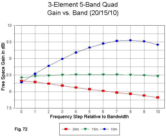
As shown in Fig. 72, the gain across 15 meters is virtually flat. The gain across 20 meters descends, but only moderately, with design emphasis upon performance at the lower end of the band. Although the 10-meter gain curve still ascends, its peak occurs within the pass band. As we discovered with 2-element multi-band quad arrays, element interaction provides 10-meters with higher gain than might otherwise be obtained in a monoband 18' boom quad, since the elements are very widely spaced for that band. 20 meters seems to "suffer" from its relative independence, with 15 meters showing a "balance" of influence. (How to quantify the terms in "-" remains a task for the future of quad design.)
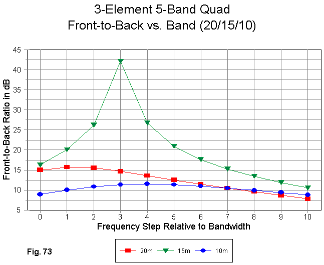
The front-to-back curves (Fig. 73) tell us that the antenna was largely designed for gain, with the source impedance the most important second factor. Front- to-back ratio was largely accepted for what it turned out to be. On 15 meters, where gain performance is exceptionally stable, the front-to-back peak can easily be moved within the passband. 20 and 10 are harder nuts to crack, and their numbers are relatively poor, except for the low end of 20 meters, where they approach being adequate. On 10, the front-to-back performance across the band is similar to a 2-element reflector-driver Yagi.

The 50-Ohm SWR performance of the antennas has also been optimized for the low ends of the bands, as is readily apparent in Fig. 74. On 20 and 10, the SWR is below 2:1 for at least 80% of the pass bands, but that figure goes down to 60% on 10 meters. For reference, here are the standard figures across each of the wide bands.
Band           Impedance at a Specified Frequency           Delta    Delta
20 m      14.0           14.175         14.35                 R        X
          45.3 - j19.9   43.3 + j 4.0   32.0 + j43.2        13.3      63.1
15 m      21.0           21.225         21.45
          48.1 - j15.6   45.4 + j 6.8   35.4 + j38.3        12.7      53.9
10 m      28.0           28.5           29.0
          76.9 - j32.2   45.0 + j14.9   27.0 + j86.7        49.9     118.9
Optimizing gain within the pass band for each of the wide bands has resulted in an expansion of the range of reactance across the bands. Like most 3-element parasitical arrays, the lowest impedance is at the upper end of the band.
We might accept the 20-15 meter performance as not likely to be improved by more than a small amount due to the limitations of the boom length on those bands. Compared to Yagis, the boom length is short for 20 meters and about right for 15 meters, relative to maximizing gain through the use of three elements. Extending and improving 10 meter performance seems the only further development possible, since the boom is long for 3 elements on that band. The 10' reflector-driver spacing seems especially long.
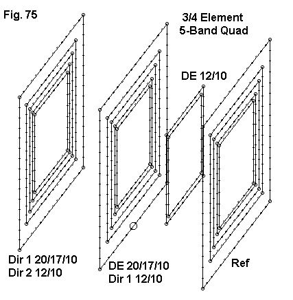
The following table lists the side lengths for the elements in this revised array.
Band      Reflector           Driver              Dir. 1             Dir.2
          Side L    Space     Side L    Space     Side L    Space    Side L
           feet     Re-DE      feet     DE-D1      feet     D1-D2     feet
20        18.084    10        17.808     8        17.084
17        14.042    10        13.858     8        13.316
15        12.066    10        11.834     8        11.500
12        10.200     5         9.932     5         9.850     8       9.892
10         9.224     5         8.816     5         8.716     8       8.666
Due to the difference in space on 12 and 10 in terms of fractions of a wavelength, the forwardmost director on 12 is actually larger than the first director. Many of the loop size changes are small on the lower bands, and the 15 meter dimensions did not change at all. Here is the model description for this 68-wire, 724-segment model.
ON7NQ 3/4 el 5 band #12                      Frequency = 14.175  MHz.

Wire Loss: Copper -- Resistivity = 1.74E-08 ohm-m, Rel. Perm. = 1

              --------------- WIRES ---------------

Wire Conn.--- End 1 (x,y,z : in)  Conn.--- End 2 (x,y,z : in)  Dia(in) Segs

1   W4E2 -108.50,  0.000,-108.50  W2E1 108.500,  0.000,-108.50    # 12   15
2   W1E2 108.500,  0.000,-108.50  W3E1 108.500,  0.000,108.500    # 12   15
3   W2E2 108.500,  0.000,108.500  W4E1 -108.50,  0.000,108.500    # 12   15
4   W3E2 -108.50,  0.000,108.500  W1E1 -108.50,  0.000,-108.50    # 12   15
5   W8E2 -106.85,120.000,-106.85  W6E1 106.850,120.000,-106.85    # 12   15
6   W5E2 106.850,120.000,-106.85  W7E1 106.850,120.000,106.850    # 12   15
7   W6E2 106.850,120.000,106.850  W8E1 -106.85,120.000,106.850    # 12   15
8   W7E2 -106.85,120.000,106.850  W5E1 -106.85,120.000,-106.85    # 12   15
9  W12E2 -102.50,216.000,-102.50 W10E1 102.500,216.000,-102.50    # 12   15
10  W9E2 102.500,216.000,-102.50 W11E1 102.500,216.000,102.500    # 12   15
11 W10E2 102.500,216.000,102.500 W12E1 -102.50,216.000,102.500    # 12   15
12 W11E2 -102.50,216.000,102.500  W9E1 -102.50,216.000,-102.50    # 12   15
13 W16E2 -84.250,  0.000,-84.250 W14E1  84.250,  0.000,-84.250    # 12   13
14 W13E2  84.250,  0.000,-84.250 W15E1  84.250,  0.000, 84.250    # 12   13
15 W14E2  84.250,  0.000, 84.250 W16E1 -84.250,  0.000, 84.250    # 12   13
16 W15E2 -84.250,  0.000, 84.250 W13E1 -84.250,  0.000,-84.250    # 12   13
17 W20E2 -83.150,120.000,-83.150 W18E1  83.150,120.000,-83.150    # 12   13
18 W17E2  83.150,120.000,-83.150 W19E1  83.150,120.000, 83.150    # 12   13
19 W18E2  83.150,120.000, 83.150 W20E1 -83.150,120.000, 83.150    # 12   13
20 W19E2 -83.150,120.000, 83.150 W17E1 -83.150,120.000,-83.150    # 12   13
21 W24E2 -79.900,216.000,-79.900 W22E1  79.900,216.000,-79.900    # 12   13
22 W21E2  79.900,216.000,-79.900 W23E1  79.900,216.000, 79.900    # 12   13
23 W22E2  79.900,216.000, 79.900 W24E1 -79.900,216.000, 79.900    # 12   13
24 W23E2 -79.900,216.000, 79.900 W21E1 -79.900,216.000,-79.900    # 12   13
25 W28E2 -72.400,  0.000,-72.400 W26E1  72.400,  0.000,-72.400    # 12   11
26 W25E2  72.400,  0.000,-72.400 W27E1  72.400,  0.000, 72.400    # 12   11
27 W26E2  72.400,  0.000, 72.400 W28E1 -72.400,  0.000, 72.400    # 12   11
28 W27E2 -72.400,  0.000, 72.400 W25E1 -72.400,  0.000,-72.400    # 12   11
29 W32E2 -71.000,120.000,-71.000 W30E1  71.000,120.000,-71.000    # 12   11
30 W29E2  71.000,120.000,-71.000 W31E1  71.000,120.000, 71.000    # 12   11
31 W30E2  71.000,120.000, 71.000 W32E1 -71.000,120.000, 71.000    # 12   11
32 W31E2 -71.000,120.000, 71.000 W29E1 -71.000,120.000,-71.000    # 12   11
33 W36E2 -69.000,216.000,-69.000 W34E1  69.000,216.000,-69.000    # 12   11
34 W33E2  69.000,216.000,-69.000 W35E1  69.000,216.000, 69.000    # 12   11
35 W34E2  69.000,216.000, 69.000 W36E1 -69.000,216.000, 69.000    # 12   11
36 W35E2 -69.000,216.000, 69.000 W33E1 -69.000,216.000,-69.000    # 12   11
37 W40E2 -61.200,  0.000,-61.200 W38E1  61.200,  0.000,-61.200    # 12    9
38 W37E2  61.200,  0.000,-61.200 W39E1  61.200,  0.000, 61.200    # 12    9
39 W38E2  61.200,  0.000, 61.200 W40E1 -61.200,  0.000, 61.200    # 12    9
40 W39E2 -61.200,  0.000, 61.200 W37E1 -61.200,  0.000,-61.200    # 12    9
41 W44E2 -59.950, 60.000,-59.950 W42E1  59.950, 60.000,-59.950    # 12    9
42 W41E2  59.950, 60.000,-59.950 W43E1  59.950, 60.000, 59.950    # 12    9
43 W42E2  59.950, 60.000, 59.950 W44E1 -59.950, 60.000, 59.950    # 12    9
44 W43E2 -59.950, 60.000, 59.950 W41E1 -59.950, 60.000,-59.950    # 12    9
45 W48E2 -59.100,120.000,-59.100 W46E1  59.100,120.000,-59.100    # 12    9
46 W45E2  59.100,120.000,-59.100 W47E1  59.100,120.000, 59.100    # 12    9
47 W46E2  59.100,120.000, 59.100 W48E1 -59.100,120.000, 59.100    # 12    9
48 W47E2 -59.100,120.000, 59.100 W45E1 -59.100,120.000,-59.100    # 12    9
49 W52E2 -59.350,216.000,-59.350 W50E1  59.350,216.000,-59.350    # 12    9
50 W49E2  59.350,216.000,-59.350 W51E1  59.350,216.000, 59.350    # 12    9
51 W50E2  59.350,216.000, 59.350 W52E1 -59.350,216.000, 59.350    # 12    9
52 W51E2 -59.350,216.000, 59.350 W49E1 -59.350,216.000,-59.350    # 12    9
53 W56E2 -55.340,  0.000,-55.340 W54E1  55.340,  0.000,-55.340    # 12    7
54 W53E2  55.340,  0.000,-55.340 W55E1  55.340,  0.000, 55.340    # 12    7
55 W54E2  55.340,  0.000, 55.340 W56E1 -55.340,  0.000, 55.340    # 12    7
56 W55E2 -55.340,  0.000, 55.340 W53E1 -55.340,  0.000,-55.340    # 12    7
57 W60E2 -52.900, 60.000,-52.900 W58E1  52.900, 60.000,-52.900    # 12    7
58 W57E2  52.900, 60.000,-52.900 W59E1  52.900, 60.000, 52.900    # 12    7
59 W58E2  52.900, 60.000, 52.900 W60E1 -52.900, 60.000, 52.900    # 12    7
60 W59E2 -52.900, 60.000, 52.900 W57E1 -52.900, 60.000,-52.900    # 12    7
61 W64E2 -52.300,120.000,-52.300 W62E1  52.300,120.000,-52.300    # 12    7
62 W61E2  52.300,120.000,-52.300 W63E1  52.300,120.000, 52.300    # 12    7
63 W62E2  52.300,120.000, 52.300 W64E1 -52.300,120.000, 52.300    # 12    7
64 W63E2 -52.300,120.000, 52.300 W61E1 -52.300,120.000,-52.300    # 12    7
65 W68E2 -51.995,216.000,-51.995 W66E1  51.995,216.000,-51.995    # 12    7
66 W65E2  51.995,216.000,-51.995 W67E1  51.995,216.000, 51.995    # 12    7
67 W66E2  51.995,216.000, 51.995 W68E1 -51.995,216.000, 51.995    # 12    7
68 W67E2 -51.995,216.000, 51.995 W65E1 -51.995,216.000,-51.995    # 12    7

              -------------- SOURCES --------------

Source    Wire      Wire #/Pct From End 1    Ampl.(V, A)  Phase(Deg.)  Type
          Seg.     Actual      (Specified)

1           8     5 / 50.00   (  5 / 50.00)      1.000       0.000       V
This model is listed by bands from 20 through 10 meters, with wires within a band given from the reflector forward. Consequently, the source wires are 20m = wire 5, 17m = wire 17, 15m = wire 29, 12m = wire 41, and 10m = wire 57. Dimensions are in inches, and the wire size is #12 AWG copper.
To see what basic improvements the addition of the two new drivers has made, let's look at the midband performance reports from the model.
          Freq.     Gain      F-B       Impedance
 Band      MHz      dBi       dB        R +/- jX Ohms
20        14.175     8.30     15.2       44.4 + j 3.6
17        18.118     8.42     25.5       43.5 - j 0.1
15        21.225     8.52     21.6       46.6 - j 0.6
12        24.94      9.22     18.5       42.2 + j 2.9
10        28.5       9.74     27.9       56.1 + j11.3
Overall, gain and front-to-back ratios are up across the board, although only marginally on the lowest bands. Mid-band gain and front-to-back ratio are better on 10 meters especially. 15-meters remains virtually unchanged.
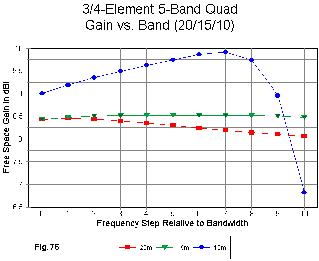
In the gain curves in Fig. 76, we may note that 15 remains unchanged in its flat curve, while the decrease in gain at the upper end of 20 meters has decreased. The gain curve for 10 meters remains at about 9 dBi or better for 90% of the pass band, before taking a nose dive.
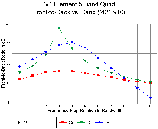
In Fig. 77, we can see the unchanged 15-meter front-to-back curve, which serves as a back drop for the other curves. 20 meters shows a movement of the curve to better center it within the band and give better upper band- edge performance. The biggest improvement occurs on 10 meters, where the front-to-back value is at least 15 dB for more than 3/4 of the pass band. As with the gain, we get a steep slope downward as the frequency approaches 29 MHz.
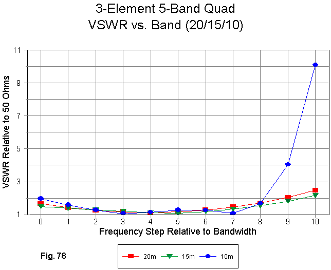
The small adjustments to the lower bands yield 50-Ohm SWR curves (Fig. 78) that are below 2:1 for 90% of 20 and 15 meters. The 10-meter 2:1 curve has been extended to over 80% of the pass band and is consistent with the patterning of the gain and front-to-back figures. 28.8 to 29 MHz has been sacrificed for optimized performance at the low and middle regions of the pass band. You may compare this figure with Fig. 74 to more clearly see the improvement in the 50-Ohm SWR category.
It is also noteworthy to compare the performance figures of the 3/4-element 5-band quad with those of the traditional design in Fig. 68 through Fig. 70. Although the 4-element, 40' boom design provides more gain on 15 and 10 meters, the 18' boom 3/4-element design is superior in all other categories, except perhaps 20-meter front-to-back ratio--which was obtained at the cost of a relatively low gain figure over most of the band. The 18' 3/4-element design is also a better match on every band.
The results of looking at these models are a few suggestions rather than judgments. First, element interaction in a multi-band quad array remains a strong candidate for being the source of some of its performance. The fact that the current ON7NQ model achieves the performance it does with a boom less than 50% the length of the more traditional model suggests that some of the element interactions can be beneficial.
The achievements of the short boom quad also suggest that those interested in quad design may wish to rethink some of presumptions underlying traditional designs. Element spacing taken in terms of fractions of a wavelength plays a role in optimizing performance, although not necessarily in a simple way. Simply adding element collections at somewhat arbitrary points along the boom may be less effective than optimizing the spacing for each major band and then working out whatever compromises may be needed. A 40' boom may be both useful and necessary for higher gain on 20 and 17, but without intermediate elements somewhere along the line, the boom length may be wasted for 10- and 12-meter performance.
Even within the realm of these design suggestions, it appears that a quad can be designed for a relatively uniform source impedance for all of the bands covered. Although this feature may not improve absolute performance, it can ease the task of installation, band-switching, and other functions of a more practical nature in constructing and using a large quad array.
There may in fact be designs available that achieve all of this. My small sample of models can make no claim to being exhaustive or even representative. However, if those designs are not available at present, then multi-band quad designers have a fertile field of endeavor for some time to come. If someone is going to erect something of the mechanical complexity of a many-element, many-band quad, he deserves to have the optimal performance to be gained from the array--and from the investment he has made in it and in its supporting structure.
Updated 2-26-99. © L. B. Cebik, W4RNL. Data may be used for personal
purposes, but may not be reproduced for publication in print or any other medium
without permission of the author.
![]() Go to Feeding Multi-Band Quads
Go to Feeding Multi-Band Quads