
Antentop is FREE e-magazine devoted to Antennas and Amateur Radio an
Special page devoted to
Building a Ground Tuner (Artificial Earth) by ZS1JHG

Custom Search
|
ANTENTOP-
01- 2020, # 024
|
Building
a Ground Tuner |
|
|
|
|
Note: This wire
needs to be as short as practically possible, ie
place the Ground Tuner side by side or on top of the Transmitter. Attach a length
of random wire to the binding post marked
Output to random length of wire (Counterpoise Wire or Ground Connection
Wire). Be careful not to reverse these wires. The random
wire should be a quarter-wave length or less at the operating
frequency. Place the random length of wire on the floor and tape up
the open end of the wire to avoid any RF burns. To obtain maximum
RF ground current for a low impedance RF ground, alternately adjust
the two controls on the front panel, the Switch for Inductance
and the Variable Capacitor. Turn the Inductance Switch first until
the highest amount of current can be seen on the RF Ammeter. Then
adjust the Variable Capacitor control to peak the amount of RF
current. Try several
inductance setting for the highest readings. What if the
needle goes off the scale or doesn't move at all? Then the sensitivity
of the Ammeter needs to be adjusted. Turn the Sensitivity pot
control until the needle is in the middle of the scale. Then readjust
the Switch for Inductance until you get the highest amount of
RF current and use the Variable Capacitor to peak the RF current.
If the needle is still off scale or zero, readjust the Sensitivity
control and repeat the tuning process. |
The Commercial
ATU an FC-125 consisted of an RF sensing circuit a large coil
a 11 position ceramic switch prewired to the switch but not
the coil. I added a 180
Pf wide spaced Variable Capacitor the largest size I could fit
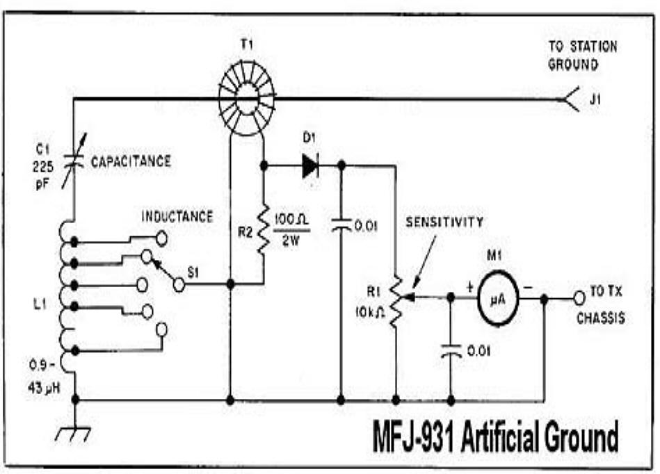
into the ATU Case and altered the wiring to the circuit shown
above. As the coil
was large I reduced it to 43 Mh
inductance and tapped the coil as per the MFJ-931 which
uses a similar sized coil/variable capacitor combination. For the lucky
builder who might have or be able to acquire an FC-125 the coil
tappings are as follows: Turns 1 to 6 tap every turn,Turns
7 to 12 tap every second turn,tap turn
20 and the last turn turn 23 (ie
1,2,3,4,5,6,8,10,12,20,23). Note the Variable
Capacitor must be insulated from the FC-125
casing . For those inquiring
minds the meter trim pot is located on the RF sensing board and
can be adjusted by drilling a small hole on the top case cover
otherwise the top cover needs to be removed each time. 73! de ZS1JHG |
|
|
|
|
|
|
|
Page- 90 |
|
 |
 |
|
 |
|
|
|||
Just for Fun:

Powered byIP2Location.com
Thanks for your time!
Last Updated:
January 30, 2021 21:16


