
|
|
 |
 |
 |
|
|
Antentop is FREE e-magazine devoted to Antennas and Amateur Radio an
Special page devoted to
Directional Antenna UA6AGW V. 7.00

Custom Search
|
ANTENTOP- 01- 2014 # 018 |
Directional Antenna UA6AGW V. 7.00 |
|
|
|
|
|
|
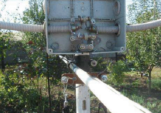
Picture 2 Mounting of the Plastic Tube and Wire Montage of the
Horizontal Wires |
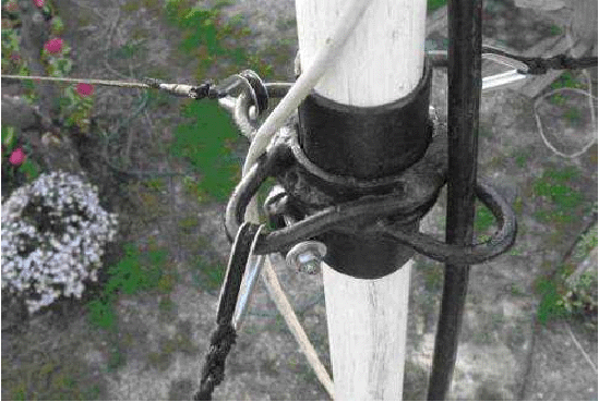
Picture 3 Jointing Mast's Tubes |
|
|
|
|
|
|
Then the cable is turned to loop. Far end
of the length is soldered to the first (left) side of the prepared
cable. (In Russia the method of the making the coupling loop sometimes
is named -method of the DF9IV-) |
The coupling loop is fastened
to the upper part of the antenna's loop with help of a Scotch
and ties. Below there are several simple rules how
to install the coupling loop. |
|
|
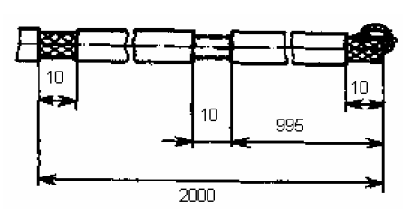
Figure 2 Preparation of the Coupling Loop for the Directional Antenna UA6AGW V. 7.00 |
||
|
At first, find on the antenna loop a point that is equidistance from left and
right side of the C2. It is the point of symmetry of the antenna. At second, find the point of symmetry
of the coupling loop. The coupling loop is mounted in the top
of the antenna loop. Point of symmetry of the coupling loop should
concur with the point of symmetry of the antenna. Picture 4 shows the coupling loop on
the antenna. At third, to
fasten with help of the cable ties the coupling loop to the antenna
loop at the distance of 6-8- cm from the point of symmetry of
the antenna loop. |
Antenna was tuned (when it was placed on mast) in height
5- meters (it is from the ground to the top of the mast). Horizontal
wires and matching box with capacitors was at 3.5- meters above
the ground. A 2- meter ladder was used by me for tuning the antenna.
Antenna works fine ever at the small height. F/B ratio was near
20-dB in this case. Antenna was tuned to 7080- kHz in mind that
the resonance frequency move up (to 7100- kHz) at the height 8-
meter. Antenna is simple to tune to the resonance. It may be tuned
with help C2 (56- pF at Figure 1) to maximum RF- voltage at the long horizontal wire
or with help receiver to maximum receiving signal. |
|
|
|
|
|
|
|
Page- 37 |
|
 |
 |
|
 |
Just for Fun:

Powered byIP2Location.com
Thanks for your time!
Last Updated:
January 5, 2020 22:41