

Antentop is FREE e-magazine devoted to Antennas and Amateur Radio an
Special page devoted to
Directional Antenna UA6AGW V. 7.00

Custom Search
|
ANTENTOP- 01- 2014 # 018 |
Directional Antenna UA6AGW V. 7.00 |
|
|
|
|
Design: Loop is made from so- called half- inch coaxial cable
with crimped copper braid. The copper braid is covered by two
layers of protection lacquer then covered by electrical protection
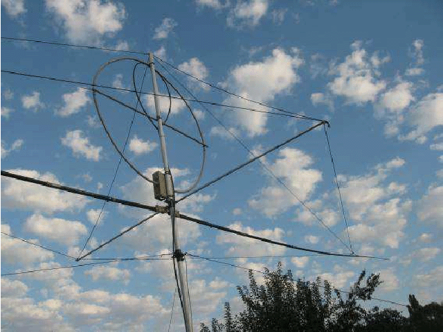
plastic tube. It is made for weather- proof sustain. Picture 1 shows the antenna. Usual plastic fishing poles are
used for the form for long wires. Inside the fishing pole a multi-cored
copper wire is going through. Thin ends of the fishing pole are
changed by light aluminum wire in diameter 8- mm. The multi- cored
wire is connected to the aluminum wire. |
Short wires are placed along plastic tube in 14- mm
diameter. The tube is not only support for the short wires. Rope
guys going from the ends of the tube to ends of the fishing poles
provided rigid of the antenna structure. Picture 2 shows mounting of the plastic tube and wire montage
of the horizontal wires. |
|
Picture 1 Directional Antenna UA6AGW
V. 7.00 |
|
|
Mast of the antenna has height in 8- meters. Two water tubes made the mast. First tube that is sitting on the ground is a metal tube in 48- mm OD. It is 5- meter long. The second one, that holds the antenna structure, is plastic tube in 42- mm OD. The plastic tube is 3- meter long. The plastic tube is inserted inside the metal tube that allows rotate the antenna. A simple home- made adaptor (made of from two pieces of metal water tubes in diameter 48- and 55- mm) is used for connection the mast's tubes. Picture 3 shows jointing of the plastic and etal tube. |
The antenna fed by a coupling loop. For
simplicity of the design the coupling loop made from the feeding
coaxial cable. Figure 2 shows the coupling loop before it is circulated to
loop. Length of the coaxial cable to be used for the coupling
loop is 200- mm. Plastic from the length of the coaxial cable
is removed on to 10- mm in the center and from two ends. Then
braid of the coaxial cable is removed at the center. Inner conductor
is soldered to the braid at the far (right) end of the length. |
|
Heading of the Article |
|
|
|
|
|
Page- 36 |
|
 |
 |
|
 |
Just for Fun:

Powered byIP2Location.com
Thanks for your time!
Last Updated:
January 5, 2020 22:41


