


|
|
 |
 |
 |
|
|
Antentop is FREE e-magazine devoted to Antennas and Amateur Radio an
Special page devoted to
Old Receiving Magnetic Loop Antennas

Custom Search
|
ANTENTOP-
02- 2004, # 006
|
Old
Receiving Magnetic Loop Antennas
|
|
|
|
||
|
a
suitcase and using a loop magnet antenna is described in the reference
[5]. Fig. 6 shows
the circuit and design of the loop antenna. It was used two magnetic
loop antennas, M1 and M2. Lengthening coils are switched in serial
with each loop antenna (L1 to M1 and L2 to M2), necessary for exact tuning
of the loops to frequencies range needed. Both, M1 and M2 are used
at LW. When the loop works at MW, M2 is shortened, and only M1 does
receiving. Magnetic antennas M1 and M2 have sizes 315x 245 millimeters, M1 contains 14 turns of Litz wire 30x0,06, M2 contains 50 turns of Litz wire 15x0,05. As a last resort, instead of a Litz it is possible to use a copper insulated wire in diameter of 0,15 millimeters. |
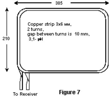
Figure 7 SW magnetic loop antenna |
|
|
|
||
|
Lengthening
inductor L1 contains 50 turns, lengthening inductor L2 contains
125 turns, the wire is Litz 15x0,05. These
inductors are reeled on a form in diameter of 8 millimeters. The
width of winding is 7 millimeters for both inductors. |
References:
4. Amateur Battery Radio Receivers. Moscow, MRB, Gosenergoizdat, 1950.
|
|
|
|
||
|
|
||
|
|
|
|
|
|
Page 92 |
|


 |
 |
 |
 |
Just for Fun:

Powered byIP2Location.com
Thanks for your time!
Last Updated:
February 23, 2020 20:15