antentopSince2 July

Ham Spirit
Free Choice


Free Antentop Amateur Open Book
Antentop Album
Antentop Survey


Antentop is FREE e-magazine devoted to Antennas and Amateur Radio an

Special page devoted to

Old Receiving Magnetic Loop Antennas

Custom Search


ANTENTOP- 02- 2004, # 006

Old Receiving Magnetic Loop Antennas


Figure 1B Old huge magnetic receiving loop antennas
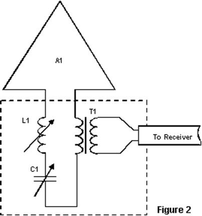


Figure 2 Connection of the reception magnetic loop to a radio receiver

main since the Broadcasting Center was in operation, so, the equipment were in continuous work already more than thirty years. Time to time the tubes of the receivers and amplifiers were changed, it was only that was done. Quality of work of the Broadcasting Center was great. The most interesting part of this Broadcasting Center was a small-sized (certainly, small-sized in comparison with the antennas shown on Fig. 1) receiving magnetic loop antenna. By nameplate from the antenna I have known, that the antenna was made in 1949 on one of plants of Gorky (now Nizhniy Novgorod), Russia. Fig. 3A shows a design of the small-sized magnetic loop, and Fig. 3B shows the electric circuit of the antenna. Design and circuit, both, were pictured by me from the real loop.  The loop antenna (item 1) had diamond shape, sides had length in 105-cm (it was measured by a roulette), the loop was attached to a wooden cross (item 2), this one was covered by light lacquer. Overall height of the magnetic loop antenna was near to 2 meters. Antenna wires were more than 1-millimeter in diameter and were covered by thick black cotton isolation, a strong thin layer of light varnish covered the isolation.
Such small- sized receiving loop I have seen in an old village Broadcasting Radio Center in Central Russia, where I was occasionally in 80s of the 20 Century. The center was build in the beginning of 50 years of the 20 Century and till now was in work practically without changes. The broadcasting center settled down in a small room on a ground floor.


This rural Broadcasting Center contained a receiver PTS (see page 93- 94 about USSRs RBC) together with a small-sized loop antenna and an old tube audio amplifier, but I could not remember its type. All equipment was produced at the 50s. As I was told, the radio receiver and the audio amplifier of low frequency never were switched off from the
The loop contained about 20 turns of the wire. The turns were rigidly settled down in trenches of plates (item 3), the plates were probably made of an ebonite. The distance between turns on the plates was equal to the diameter of the wire. The loop antenna was coupled to a receiver through a coupling loop (item 4) that contained 4 turns. The coupling loop was connected to a receiver through a feedline (item 5). The feedline has length near 3 meters and looks like a main wire.


A small wooden box (item 6) was in the bottom of the loop. A big three-section (each section has 12-500-pF) variable capacitor with vernier intended for tuning the loop to a resonance was in the box. Also there were taps switch S1 and two trap (L1C2 and L2C3) tuning to hindered broadcasting radio stations. The trap is


http://www.antentop.org/

Page 88


87 88 89 90 91 92


QRP Transceivers and PA from Accessible Parts IP for QRP Antentop Book Radio Antenna Engineering Book Antentop Printed and e- magazines


Just for Fun:

Map IP Address
Powered byIP2Location.com

Thanks for your time!

Last Updated:

February 23, 2020 20:02

Antentop Home Page

Free Antentop Open Book