


|
|
 |
 |
 |
|
|
Antentop is FREE e-magazine devoted to Antennas and Amateur Radio an
Special page devoted to
Old Receiving Magnetic Loop Antennas

Custom Search
|
ANTENTOP-
02- 2004, # 006 |
Old
Receiving Magnetic Loop Antennas
|
||
|
|
|||
|
|
|||
|
|
||
|
|
Igor Grigorov, RK3ZK |
||
Receiving magnetic
loop antennas were widely used in the professional radio communication
from the beginning of the 20 Century. Since 1906 magnetic loop
antennas were used for direction finding purposes needed for navigation
of ships and planes. Later, from 20s, magnetic loop antennas were
used for broadcasting reception. In the USSR in 20- 40 years of
the 20 Century when broadcasting was gone on LW and MW, huge loop
antennas were used on Reception Broadcasting Centers (see
pages 93- 94 about USSRs RBC). Magnetic loop antennas worldwide were
used for reception service radio stations working in VLW, LW and
MW. The article writes up several designs of such old receiving
loop antennas.
|
|||
|
|
|
||
LW- MW Huge Receiving Loop Antennas for Broadcasting
and Direction Finding
In
old radio textbooks you can find description of old magnetic receiving
loop antennas. As a rule, old magnetic receiving loop antennas
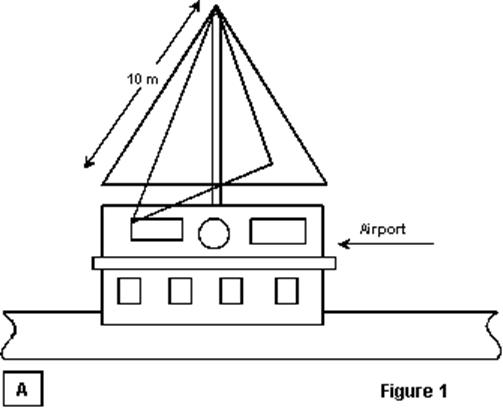
had a triangle or square shape, a side of the triangle or square
had length in 10-20 meters. The huge square was put on to a corner.
The distance from the ground up to lower wires of the magnetic
receiving loop usually was not less than 4 meters.
Fig. 1A shows a triangular receiving loop antenna consisting
of two perpendicular loops, used for direction finding at airports
[1], Fig. 1B shows a square receiving loop antenna
used on Broadcasting Radio Centers of the USSR at the end of 30s
of the 20 Century [15].
Usually the receiving magnetic loop contained from one up to eight
turns. |
Fig. 2 shows a typical connection of the above mention huge
magnetic receiving loop antennas designed for working on one fixing
frequency to the receiver. To a resonance the loop A1 is tuned
by lengthening coil L1 (sometimes two lengthening coils switched
symmetrically to both side of the loop were used) and variable
air- dielectric capacitor C1. T1 did connection with antenna feedline.
L1, C1 and T1, as a rule, are placed directly near the antenna
keeping minimum length for wires from the antenna to the parts.
Certainly, there were others circuits for connection magnetic
loops to a receiver, but the circuits were insignificantly distinguished
from Fig. 2. Small- Sized Magnetic Loop of a Local Broadcasting
Radio Center Huge loop antennas were used for cities Broadcasting Radio Centers, for local Broadcasting Radio Centers a small- sized loops were used. |
||
|
|
|||
|
|
|||
|
|
|
||
|
|
|
||
 |
 |
 |
 |
Just for Fun:

Powered byIP2Location.com
Thanks for your time!
Last Updated:
February 23, 2020 20:00