


|
|
 |
 |
 |
|
|
Antentop is FREE e-magazine devoted to Antennas and Amateur Radio an
Special page devoted to
J - Antenna for 160,15 and 10(FM) meters

Custom Search
|
ANTENTOP-
02- 2003, # 003 |
J - Antenna for 160,15 and 10(FM) meters |
|
|
|
||
|
random wire with
length of several meters... Simply it can be understood, that
on doubling the working frequency the matching line is completely
out of resonance, and works as a 'short' for the transmitter.
But everything has advantages, and this fact means not only impossibility
to work on 80 m, which is definitely bad, but also deep suppression
of 2- nd harmonic by working on 160
m, which is really well. Almost
the same situation is on 40 m band. Here the active component
of input impedance of the antenna (measured by noise bridge) is
also quite low (several Ohms), and no resonance exists inside
or near amateur frequencies. But
if you try to work on this antenna on 15 and 10 meters bands,
the situation is more optimistic. In my case, on 21430 KHz the
SWR was about 1.3:1 and increases to 2.5:1 when moving down to
21000 KHz. Measured impedance was about
55 Ohm with a low capacitive reactance. From first sight, it is
quite strange, but nevertheless, antenna behaved well on this
band, and using just 10 W of power, I was able to make long-distance
QSO's even with North America. The most interesting fact was,
that this was "true" |
resonance of the antenna,
without any participation of the feeder (SWR did not change significally when the feeder length was alternated). In contrast to this, on 10 meters band the antenna behaves very poor-
the air seems to be empty, and even common industrial noise is
received with a level comparable to internal noise of the receiver.
Compared to the special 10 meters antenna (see above), the signal
of distant correspondents were weaker by 10-20 dB (!), and on
transmission even my neighbors gave me reports like 53-54. However,
when frequency was moved up to 29 MHz and higher, the efficiency
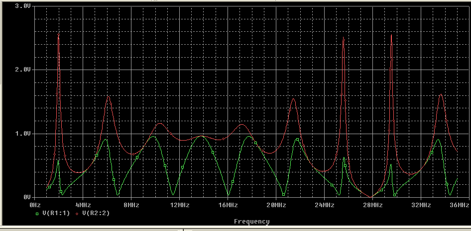
improved dramatically. To understand this phenomenon, some calculations were performed. First
of all, it was found, that frequency response of the matching
line with a resistive loading (see Figure
3) in range 1.5-32 MHz has many maxima, and one of
them is inside 15-m amateur band (Figure
5, red trace). Another maxima is near 29.5 MHz- in the upper part of 10-m band. |
|
|
Figure 5. Frequency response of the matching
line in whole HF range |
||
|
I
guess, that these results may be assumed
at least as a qualitative explanation of the antenna behavior.
I say "qualitative" because the whole system can not
be adequately represented by a matching line with a resistor at
the end- impedance of the antenna wire also should be taken into
account. However it is clear, why besides 'native'band, antenna
works well on 21 MHz, and why on frequencies about 28500 there
is a minimum of performance, which rapidly increases when moving
up to 29 MHz. |
Conclusion As a conclusion
is can be said, that LW antenna with a coaxial matching line (J-antenna),
which is designed for 160 m band, can do perfect job on 15 meters
and on a part of 10 meters band also without any switching and
tuning devices. Of
course, the efficiency on 'upper' bands is be substantially lower,
that on 'native' one due to RF losses in the matching line (which
actually works with a very high SWR). But to my mind it is still
acceptable, especially in the case, when there are no conditions
to mount huge and efficient antennas. |
|
|
|
|
|
|
|
Page 49 |
|
 |
 |
 |
 |
Just for Fun:

Powered byIP2Location.com
Thanks for your time!
Last Updated:
March 6, 2020 22:00