


|
|
 |
 |
 |
|
|
Antentop is FREE e-magazine devoted to Antennas and Amateur Radio an
Special page devoted to
J - Antenna for 160,15 and 10(FM) meters

Custom Search
|
ANTENTOP-
02- 2003, # 003 |
J - Antenna for 160,15 and 10(FM) meters |
|
|
|
||
|
Such antenna with feeding 'from the end' is much more easy to make, that a simple dipole. Here, antenna wire bears only itself, and this reduces the mechanical strength and thickness of the wire to be used. Also, you may use your window as one the point of antenna fixing. In this case, all the cable will be inside your shack and antenna could be tuned precisely in comfortable conditions. If the beginning of antenna is |
outside the apartment, most part of matching line can be used as the continuation of the feeding cable. On
Figure 2 there is a design,
that I implemented for using on 160 m amateur band, and which,
to my mind, is a perfect solution for the people, who cannot mount
a classical dipole. |
|
|
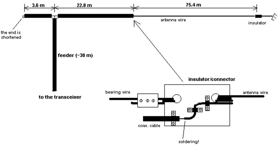
Figure 2. Long wire antenna for 160 m with a coaxial matching
line. |
||
|
In
my case, all coaxial cables have 75 Ohm impedance, the antenna
wire, as well as two bearing wires are made from very hard bimetallic
insulated cable (outer diameter is about 3 mm). The trickiest
part - the connector between cable and antenna - is shown on Figure 2.. It should be noted, that voltage on it is quite
high, and so everything should be well insulated from each other.
It is good idea to place this connector somewhere indoors, otherwise
rains and snow may cause decreasing of insulation efficiency and
antenna performance. This antenna uses a tuned line made from
the coaxial cable, and for proper operation of the whole system
the antenna wire should have the length equal to the l*0.95/2, and the coaxial
line must resonate on the working frequency. It is a good idea, to connect the shortened end of the matching line to the ground (cold water pipe, heating system, building elements etc.) to provide adequate safety and to reduce possible TV/RF interferences while transmitting. Tuning
and adjusting of the antenna
To achieve
what was declared in the previous paragraph, first of all the
precise length of the matching line should be determined. Theoretically,
it should be |
closed to l/(4*sqrt(d)) (sqrt - Square Root, d - dielectric constant of the insulator
used in the coaxial cable). SQRT(d) value
is typically about 1.52 for most cables with polyethylene-based
dielectric, that is why, 'shortening coefficient' is about 0.66.
But the practical value will be a little different from that. The lengths indicated on Figure 2 are mine values, and they can be used
as the approximate reference. Exact numbers depends on the antenna
environment and should be determined experimentally. It should
be noted, that in 'ideal'case it is not a simple task, because
in such system three values have to be varied (one is antenna
length, and another two are lengths of the parts of the matching
line). But as it appeared from my experience, for practical purposes
the most important thing is to choose correct total length of
the matching line, which must resonate on the desired frequency.
To do this,
I suggest to use the following technique.
To make your line resonate on the middle of the band (1890 kHz),
you first have to make the line about 1 m longer, that estimated
length of the tuned line (for example, 24 m), making shortened
segment about 3.6 m. Then, connect the 2-3 kiloohms resistor to the 'open' end of the line, and |
|
|
|
|
|
|
|
|
|
 |
 |
 |
 |
Just for Fun:

Powered byIP2Location.com
Thanks for your time!
Last Updated:
March 1, 2020 22:38