

There are some interesting differences in the azimuth pattern between a Moxon Rectangle and a Yagi. Here, Yagi means a reflector-driver 2-element parasitic beam, which is comparable to the reflector-driver structure of the Moxon Rectangle.
As a comparison between the structures of the two antennas, Fig. 1 shows the dimensions and relative sizes of #14 AWG copper wire antennas cut for 14.175 MHz. The frequency is somewhat arbitrary, but the choice of wire construction is not. Much of what follows will be applicable to lower HF versions of these antennas, where wire construction is the norm.
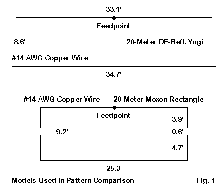
In simplicity, the Yagi has the advantage, since laying out a 2-element wire Yagi requires only the we support the wire ends at about the right spacing. The Moxon is structurally more complex, because the dimensions include a fairly critical gap distance between the driver and reflector tails. Hence, maintaining the tail lengths and gap space become important.
In size, the Moxon has the advantage, since it fits in a space about 70% as large as the Yagi. Hence, it is suited for more cramped quarters or smaller back yards for any given frequency. For example, a 40-meter version would be only about 50' from side to side, in contrast to the 67' width of a Yagi.
Most 2-element driver-reflector Yagis with a spacing of about 1/8 wl will have a feedpoint impedance between 30 and 35 Ohms. Although for narrow frequency spans, we may directly feed them with 50-Ohm coax, the operating bandwidth benefits from the use of a matching network, such as the gamma or beta. To achieve a Yagi feedpoint impedance close to 50 Ohms, the spacing should be increased to about 0.15 wl. This move, however, will result in slightly reduced gain and front-to-back figures. In contrast, the Moxon Rectangle can be designed for a direct 50-Ohm feedpoint match and will exhibit good operating bandwidth. Even in wire, the 20-meter Moxon will cover all of the band.
There are also differences in the azimuth patterns of the two antennas. The Moxon tails produce radiation to the sides, since the current in these portions of the antenna is not negligible. The tip-to-tip coupling, when combined with the mutual coupling of the parallel parts of the elements, yields a current magnitude and phase on the rear element that is nearly ideal for maximum front-to-back ratio. When we model these antennas in free space, we see comparative patterns like the ones in Fig. 2.

The Moxon will always have slightly less gain than a comparable 2-element Yagi. However, the front-to-back ratio will also always be very high in comparison--up to 20 dB better at the design frequency. In addition, the Moxon pattern is faintly cardioidal, meaning that the maximum front-to-side ratio points do not occur at 90 degrees from the maximum forward gain direction. Instead, they occur 15 to 20 degrees further back in the pattern. Hence, there is a potential for reception and transmission to the antenna sides. Even the -3 dB horizontal beamwidth of the Moxon is about 10 degrees wider than that of the Yagi.
The combination of factors that make up the Moxon and Yagi patterns present the user with choices. Which antenna may be considered superior depends in great measure (and apart from structural considerations) on the operating specifications set for a given station. For example, some operations may call for a single direction fixed beam with one direction favored, but not exclusively, over the opposite direction. The 2-element Yagi permits operation off the rear of the beam at a deficit of about 2 S-units.
In contrast, some operations may call for the maximum rejection of signals to the rear, with the widest forward beamwidth obtainable. In such cases, the Moxon Rectangle would be the option (of the 2 listed here). Indeed, the antenna can be designed for switching directions. See "Two-Element 40-Meter Switched Beam" by Carrol Allen, AA2NN, in The ARRL Antenna Compendium, Vol. 6, pp. 23-25, for an example of the techniques involved.
The final decision in the selection of any antenna requires that the station designer develop a set of operating specifications regarding antenna performance. Only by placing the specifications next to a set of antenna potentials can the operator designate one antenna type as superior to another type. The specifications and potentials lists may include both structural and performance considerations. And, of course, the final decision may involve one or more compromises.
Although NEC models cannot evaluate performance over irregular terrain, they can give some comparative guidance for performance over ground at various heights. Let's look at patterns for the two antennas at various heights below 1 wl.
I shall present information for each height in two ways. First, comparative azimuth patterns will show the outlines that indicate relative antenna performance. Second, some tabular data will allow us to zero in on some similarities and differences. The data will include the maximum gain in dBi, the 180-degree front-to-back ratio, antenna gain to the rear (listed as 180-degree gain) in dBi, and the antenna gain at right angles to the maximum forward power direction (listed as +/-90-degree gain) in dBi. As well, the tabulated data will include the elevation angle of maximum radiation (TO angle) in degrees and the -3 dB horizontal beam width in degrees. For pattern analysis, we may ignore some other data, such as the feedpoint impedance, especially since that value does not change radically from the free space value. The difference line in the tables will always subtract the Yagi values from the Moxon values. Note that the TO angles at the same throughout for both antennas.
1. 0.375 WL: We can begin with a 3/8 wl height, since many lower HF horizontal beams are used in this vicinity. Moreover, as Fig. 3 shows, the high Yagi front-to-side ratio almost disappears.

For the Yagi and Moxon at a 3/8 wl height, the tabular data is as follows:
Antenna   TO Angle  Max. Gain F-B       +/-90 Gain     180 Gain  Hor. B/W
Yagi      33        9.9       13.0      -4.7           - 3.1     75
Moxon     33        9.5       28.3      -2.8           -19.8     85
Mox-Yag             -.4       15.3       1.9           -16.7     10
At a height of 3/8 wl, the Yagi has nearly a half dB more gain. However, the front-to-back ratio at 180 degrees is over 2 S-units lower. The Moxon beamwidth is about 10 degrees wider, but at the 90-degree points, there is less than 2 dB difference.
2. 0.5 WL: As we elevate the antenna by an eighth of a wavelength, both patterns begin to develop trends that lead eventually to the free-space pattern back in Fig. 2. We can detect the trends in Fig. 4.
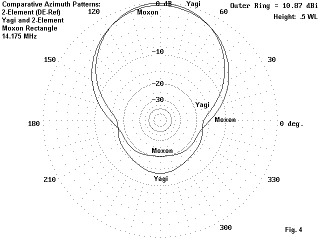
For the Yagi and Moxon at a 1/2 wl height, the tabular data is as follows:
Antenna   TO Angle  Max. Gain F-B       +/-90 Gain     180 Gain  Hor. B/W
Yagi      26        10.9      13.5      -6.0           - 2.7     73
Moxon     26        10.5      20.0      -3.8           - 9.4     82
Mox-Yag             - .4       6.5       2.2            -6.7      9
At a height of 1/2 wl, the Yagi shows the same gain advantage as at the lower height. Its front-to-back ratio improves, while the Moxon value decreases, resulting in a net difference of about 1 S-unit. The front-to-side ratio shows a slow growth in the Yagi, so that the Moxon is a little over 2 dB stronger at the 90-degree points. The beamwidth differential remains essentially the same.
3. 0.75 WL: At a 3/4-wl height, both antennas continue the emergence of their characteristics, with the Yagi developing distinct side nulls. The Moxon, on the other hand, shows a better front-to-back pattern, as seen in Fig. 5.

For the Yagi and Moxon at a 3/4 wl height, the tabular data is as follows:
Antenna   TO Angle  Max. Gain F-B       +/-90 Gain     180 Gain  Hor. B/W
Yagi      18        11.3       9.7      -11.0            1.6     70
Moxon     18        10.9      22.2      - 6.2          -11.3     79
Mox-Yag             - .4      12.5        4.8          -12.9      9
The Yagi gain advantage remains constant at 0.4 dB, while the 180-degree Moxon front-to-back advantage has regrown to over 11 dB (nearly 2 S-units). Note the difference between the front-to-back ratio, which gives a measure of relative signal strength from the front and rear, and the 180-degree gain, which compares "absolute" signal strength from the rear. These values will differ by the differential in the forward gain of the arrays. The 90-degree gain value differential has grown to nearly 5 dB, approaching an S-unit of difference.
4. 1.0 WL: At 1 wl up, both antenna azimuth patterns continue to look more and more like their corresponding free-space patterns--but not completely. As shown in Fig. 6, the Moxon does not achieve its free-space front-to-back ratio, and the Yagi does not achieve its free-space front-to-side ratio.
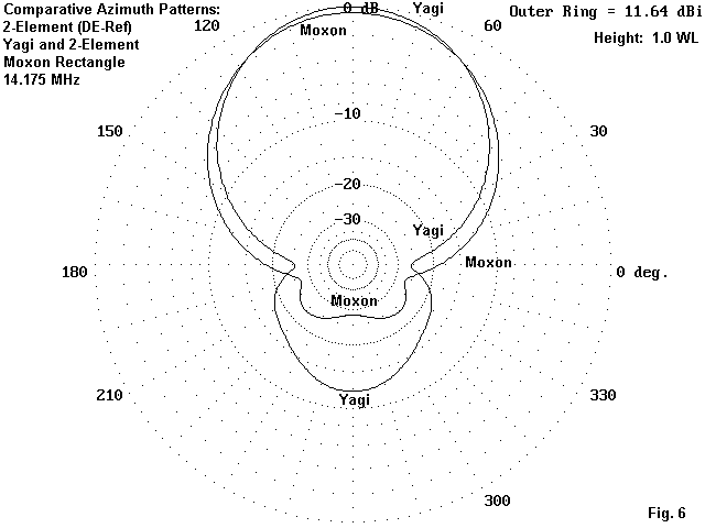
For the Yagi and Moxon at a 1.0 wl height, the tabular data is as follows:
Antenna   TO Angle  Max. Gain F-B       +/-90 Gain     180 Gain  Hor. B/W
Yagi      14        11.6      12.1      -13.9           -0.5     68
Moxon     14        11.2      27.6      - 6.9          -16.4     78
Mox-Yag             - .4      15.5        5.0          -15.9     10
The Yagi has the same 0.4 dB gain advantage, but the Moxon front-to-back ratio advantage has grown to over 15 dB--approaching 3 S-units. The ability of the Moxon to hear at a 90-degree angle to the main lobe is now at the 5 dB better mark relative to a Yagi, and something approaching an S-unit can make a considerable difference in weak signal operation.
Overall, except for the 1/2 wl height, the Moxon has by far the stronger front-to-back pattern, while the Yagi has a consistent small edge in gain. The Moxon shows an ability to utilize its wide beam width to some advantage when used as a fixed beam, especially as the antenna height is increased--something likely in the upper HF region but less likely in the lower HF realm. There is no difference in TO angles.
In the end, one can read out the numbers for any proposed height of operation between the Yagi and the Moxon (or between any other pair of possible antennas). By placing these numbers against the initial operating specifications, one can select the antenna that will best fulfill the purposes of the station. This exercise is simply a sample of what every station should ultimately do in the process of selecting antennas. Of course, one cannot neglect structural and financial considerations in the final evaluation. Nonetheless, comparing azimuth patterns at the intended height of operation can go a long way toward translating free-space abstractions into real planning tools.
Updated 2-22-2000. © L. B. Cebik, W4RNL. Data may be used for personal purposes, but may not be reproduced for publication in print or any other medium without permission of the author.