

Since the article and the posting appeared, I have heard of successful constructions of Moxon's, one for a Field Day Novice station. I have also had two types of requests. One has asked for dimensions for other bands. The other inquiry wondered if the feedpoint impedance might be brought closer to 50 ohms. The original design showed a feedpoint impedance close to 80 ohms.
I remodeled the antenna with good results on both counts. Table 1 provides dimensions for the Moxon rectangle for 40 through 10 meters. The dimensions are not perfect simple scalings, because the length-to-wire- diameter ratio changes for each ham band.
                  Table 1.  Moxon Dimensions for 40 - 10 Meters

Band     Design                      Dimension  (feet)
       Frequency (MHz)   A              B         C         D        E

10        28.50          12.44          1.94      0.41      2.41     4.76

12        24.94          14.22          2.22      0.46      2.76     5.44

15        21.20          16.72          2.63      0.52      3.25     6.40

17        18.12          19.56          3.10      0.59      3.80     7.49

20        14.17          25.00          4.00      0.72      4.85     9.57

30        10.12          35.00          5.60      1.00      6.80    13.40

40         7.15          49.56          8.01      1.33      9.63    18.97

Note:  all models composed of #14 copper wire.
All of the antennas exhibit feedpoint impedances between about 56 and
58 ohms, a close match to the standard amateur 50-ohm coaxial cable. Free space
gain and front-to-back ratio are consistent for all the models, averaging
5.8 dBi and greater than 32 dB in free space, respectively, at the design frequency,
centered in each band. Figure 2 shows a typical free space azimuth pattern for the antenna.

All of the models use #14 copper wire, although the various factors that contribute to the Moxon pattern tend to cancel out as wire size increases. Hence, a tubing model will have dimensions close to those for a thin wire model. However, it will exhibit a broader SWR bandwidth. The models were constructed on EZNEC Pro, a NEC-4 implementation by W7EL.
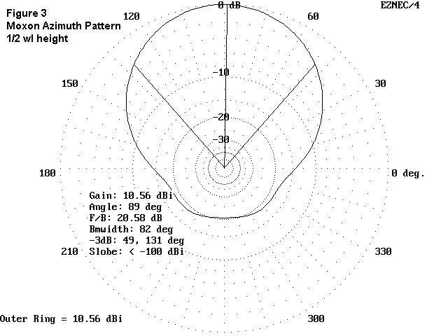
At heights below 1/2 wavelength, the front-to-back ratio will deteriorate somewhat, but usable values can be obtained. Figure 3 shows the azimuth pattern of a Moxon Rectangle at the elevation of maximum radiation, with a height of a half wavelength above real, medium ground. The pattern (especially front-to-back ratio) improves toward free space values as the antenna is further elevated. Elevation angle of maximum radiation is the same as a 2-element Yagi at the same height, for example 25° at 1/2 wl up, 14° at 1 wl up. etc.
The bandwidth for 2:1 SWR is only about 100 kHz on 40 with #14 wire. Above 40, the 2:1 SWR bandwidth covers the entire amateur band. For 30 and up, the front-to-back ratio is better than 15 dB across the band.

The original article showed one construction technique for 10 meters. Many others are possible, whether the material is wire or aluminum tubing. I shall leave the exact methods to the reader's ingenuity.

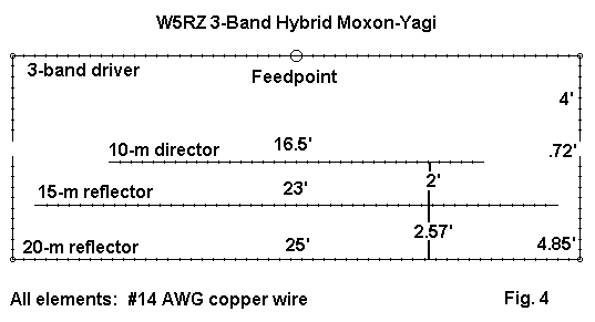
The design frequency performance for each band is summarized in Table 2. All values are based on free-space models.
     Table 2.  Modeled Tri-band Performance of the W5RZ Hybrid
Frequency	Gain (dBi)	F-B (dB)	Feedpoint Impedance
  14.15		  5.8		 34.0		  60 - j   2
  21.2		  6.4		  9.7		 180 + j 935
  28.4		  5.8 (rev)	 16.9		2100 + j3060
The antenna is designed to be fed with parallel transmission line and to be matched by a balanced antenna tuning unit. Free-space modeling of the antenna design shows that on 15 meters, the drive provides a double-humped current distribution, with a high reflector current on the 15-meter element. Current on the 10-meter element and the 20-meter reflector is low. On 10-meters, the current distribution is typical of a 1-wl element, with high director current on the 10-meter element.
This is just one possible direction of exoanding the capabilities of the Moxon Rectangle, and the future is likely to see additional examples of antenna design ingenuity, using the rectangle as the foundation.
First printed in QRPp, December, 1995. Updated and enlarged 6-10-99. © L. B. Cebik, W4RNL. Data may be used for personal purposes, but may not be reproduced for publication in print or any other medium without permission of the author.