 An Aluminum 2-Element Moxon Rectangle
In fact, there is an antenna that fits this category almost perfectly. Imagine an antenna with the gain (over real ground) of a 2-element Yagi (11+ dBi), the front-to-back ratio of a 3-element Yagi (>20 dB from 28.3 to 28.5 MHz), and an SWR of below 2:1 from one end of 10 to the other. In fact, imagine that the antenna has better than 15 dB front-to-back ratio all the way down to 28 MHz and still has about 12 dB front-to-back ratio at 29.7 MHz. (All figures are free space modeling estimates, except gain.) Imagine also that the antenna can be directly connected to 50-ohm coax with no matching system whatsoever (even though I always recommend a 1:1 choke balun). Imagine also that you can make it yourself from hardware store materials, that it will weigh about 10 pounds including the boom (under 5 pounds without the boom), and that you can make it in your garage with no special tools. Imagine also that when it is done, you will still have change from a $50 bill.
The antenna is the Moxon rectangle. Past versions that I built using wire elements required lots of PVC to support them. See "Modeling and Understanding Small Beams: Part 2: VK2ABQ Squares and Moxon Rectangles," Communications Quarterly (Spring, 1995), 55-70. Those versions were to prove the principles of the Moxon rectangle, not to produce an easy-to-build antenna.

However, if we translate the antenna into hardware store aluminum tubing, we can easily build a 1-boom version. Now peak at the sketch of the pieces. (Note: to get the detail into the figure, I had to make it a bit too large for 640-wide screens. Hence, it may not print well unless you download it and print it out landscape.)
Some 7/8" and 3/4" diameter aluminum tubing form the main elements, with 3/4" tubing for the side elements. The corners can use radius-bent tubing or be squared by making some corner supports from L-stock. Cut the straight tubing at 45-degree end angles and use 1/16" thick L-stick to fashion over and under supports. About 1-2" length each way with stainless steel sheet metal screws or pop rivets will solidify the corners with minimal weight. I even tried 1/2 inside conduit Ls, but had to ream out the ends to accept the 3/4" tubing.
The corners I used were 7/8 aluminum radius-bent sections sent to me by N6BT (of Force 12) to speed up the experimentation. You can bend your own by filling the aluminum tube with sand (or cat litter in a pinch) and bending around a 6" or larger wheel or pulley. Work slowly. Keep the sand well packed in the tube to prevent pinch bends.
The combination of 7/8" and 3/4" aluminum tubing lets you telescope the ends into the center for a precise fit or a center frequency adjustment. A similar advantage accrues from using 1" and 7/8" hardware store aluminum tubing.
The side-to-side length is the key to centering the SWR curve for lowest reading at about 28.4 to 28.5 MHz. The center frequency changes about 150 kHz for every 1" of length adjustment. Hence, using the U-shaped outer ends as trombone slides will let you center the antenna anywhere in the 10 meter band. If you use slightly larger stock, say 1" and 7/8" hardware store aluminum tubing, performance will change very little. With 7/8" tubing for the outer main elements and the sides, you can weld or otherwise fasten (with Penetrox or another bi-metal conductor/protector between metals) 3/8" copper plumbing pipe Ls as the corners.
Since the end spacing and alignment is critical to make the antenna give its full performance, you can slide a piece of CPVC or similar lightweight, durable tubing either inside the ends or over the ends and lock them in place with sheet metal screws. The rigid spacer is also a good idea to limit the twisting force placed on the curved or right-angle corners. Sheet metal screws also connect the 3/4" and 7/8" tubing together. Be sure that all hardware screws are stainless steel. "Pop" rivets will also do well, if you use the sturdiest kind.
The feedpoint assembly is not shown in the sketch. I used a very simple system. I cut one side of the driven element tubing 1" short at the feedpoint. I then cut a 2" section of 1/16" thick L-stock, and cut a 5/8" diameter hole at one end. A chassis-mounting female coax connector (with a lock washer) fits into the hole, with the plug-side pointed at the mast. stainless steel sheet metal screws attach the "extra-inch" side of the L-stock to the cut-off tube. A #14 copper wire (tinned the entire length) goes from the center pin to the other side of the feedpoint, where it is fastened under another sheet metal screw. You can devise your own more durable set of feedpoint connections. After testing but before committing the antenna to permanent installation, be sure to waterproof the rear of the coax connector as well as the coax plugs.
For element-to-boom plates, you can use any durable material. Spar varnished 3/8" plywood or LE plastic make good plates. About 3" by 9" (or longer) plates give ample room to U-bolt the elements to the plate and have room for U-bolts that go over the mast. My test model used 1/2" PVC electrical conduit U-straps fastened in place with #8 stainless steel hardware. Since 7/8" tubing stesses these straps a bit too much, I placed an extra washer between the U-strap and the plywood plate. The object is a very firm grip, but not a broken strap. Two straps hold the reflector center tube in place, but the driven element requires two on each side of the feedpoint.
As with all good antenna structure, let the elements hang under the boom. What boom? Well, almost anything, from 1-1/4" nominal diameter PVC (which I had on hand) to a good grade of aluminum tubing (thicker-wall than the usual 0.55" hardware store variety--or two pieces nested) to a 5' length of spar varnished 1.25" diameter closet rod. Make up a boom-to-mast plate similar to the boom-to-element plates, only a bit more square, and you are in business. PVC is the heaviest; aluminum the lightest, but at 5', the boom weight is not a significant issue.
The dimensions of the antenna in the drawing are too fussy, being direct translations of the computer model used to generate the antenna. Just try to keep the dimensions within about 1/4" of the drawing, and no one will be able to tell any difference in performance. Squaring the corners or missing the dimensions by a half inch will shift the performance centers by about 100 kHz at most. In most cases, you will not be aware of any difference at all. To assure that the assembly is neatly squared and close to the prescribed dimensions, you can draw the outer dimensions and center line on the shop/garage/basement floor with a marker pen and then assemble the pieces within those boundaries. As "they" always say, measure twice, cut and assemble once.
Note that the antenna is just about 12.7' wide and under 5' front-to-back, for a turning radius of about 6'8" or so. Strapped up on the side of the house, the antenna is unlikely to overhang the neighbor's yard line. The antenna is light enough for hand rotating, but an old TV rotator might come in handy. Because of the antenna's characteristics, you may not need to rotate it much.

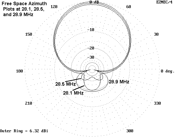
The free-space azimuth patterns for 28.1, 28.5, and 28.9 MHz show the possibilities for the Moxon rectangle. Note the very broad forward lobe that is almost a cardioid, giving reception and transmission as wide as your peripheral vision. Behind you is silence--or at least a large dose of silencing. Les Moxon, G6XN, uses a wire version of the antenna with both elements remotely tuned: that way he works the world just by electrically reversing front and rear elements with a fixed mounting. Note also that the performance characteristics promise to hold up well across the most active part of 10-meters.
But what about performance at real heights above ground?

At 35' up, about 1 wavelength, the antenna provides most of its free space performance across the band. At higher mounting levels, the performance moves closer to free-space patterning. The elevation angle at 35' for maximum gain is 13-14 degrees.

Even at 20' up, a typical portable antenna height at 10 meters, the antenna continues to display excellent front-to-back characteristics with the gain of a 2-element Yagi (which does not have good front-to-back characteristics at this height--perhaps 9-10 dB or so). The elevation angle of maximum radiation is about 23 degrees at the 5/8 wavelength height.

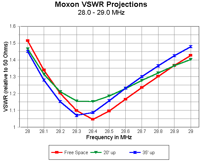
The Moxon rectangle is quite stable with respect to feedpoint characteristics as the antenna is raised and lowered. The curves actually flatten some over real ground. Therefore, setting up the antenna for operation is simple.
My own initial procedure was to fasten the antenna to a 20' mast propped up by a sturdy tripod. The reflector was no more than 5' above ground. I then adjusted the side-to-side length to minimize SWR at 28.45 MHz, sing the trombone-slide end sections. After fastening down the sections and raising the antenna, there was no detectable difference in SWR performance from the adjustment position pointing at the sky.
For a view of the complete antenna on its test mast, click here.
For a close-up of the feedpoint assembly, click here.
Contrary to claims made for the VK2ABQ, these antennas do not like to be nested for a multiband array. Even stacking requires a minimum of 10' or more between 10 and 15 meter models. However, you might consider back-to-back 10 and 15 meter antennas. A 13' boom would hold both antennas, reflector-to-reflector with minimal interaction.
It is unlikely that anyone will ever produce this beam commercially, since it is a monobander without the super gain that avid DXers and contesters crave. You can only get that kind of performance from many Yagi elements. However, you can build your own compact antenna with a pretty good chance of success on the first try. It will beat a fixed wire dipole or a dry-land vertical hands down at 20 meters and up. It also makes a dandy Field Day antenna. So if you need a compact 10-meter beam for your compact home site, then you might roll your own version of the aluminum Moxon rectangle.
So why am I placing this item at the web site rather than sending it off to a magazine? My usual outlets have a backlog of items, and the article would not appear for over a year. Sunspots are approaching for 10 meters, and a year would perhaps force some folks to wait too long. Antenna-building season is upon us. In short, this seemed the best way to disseminate the information in the shortest time. If you have a friend who needs a shortened, but full performance 2-element antenna, and who does not have web access, pass along a copy.
Updated 4-6-98. © L. B. Cebik, W4RNL. Data may be used for personal purposes, but may not be reproduced for publication in print or any other medium without permission of the author.