 Half-Length 80-Meter Vertical Monopoles:
 35V10 35V15 35V20
35VS10 35VS15 35VS20
35VC10 35VC15 35VC20
35VC10A 35VC15A 35VC20A
Antenna     Diameter    Length      Gain       Feedpoint Impedance
Filename    in inches   in feet     in dBi     in R ± jX ohms

35V10       1.0"        65.97'      5.15       35.98 - 0.32
35V15       1.5"        65.9'       5.15       36.03 - 0.54
35V20       2.0"        65.8'       5.15       36.09 - 0.19
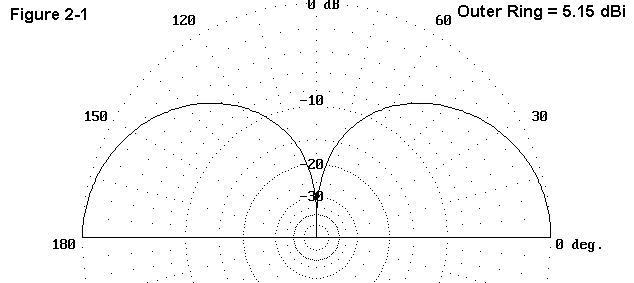
Figure 2-1 shows the elevation pattern for this model (35V20), which is standard for all subsequent models, except those specifically noted. As expected, the horizontal field component is nonexistent.

The SWR curves for a full-size vertical show little variation with changes in element diameter. SWR and feedpoint impedance (Z=R±jX in ohms) are rounded to one decimal place.
Antenna     Feed  3.5 MHz     3.55 MHz   3.6 MHz     3.65 MHz    3.7 MHz

35V10       SWR   1.7         1.3        1.0         1.3         1.6
            Z     32.9-17.8   34.4-9.1   36.0-0.3    37.6+8.4    39.4+17.1
35V15       SWR   1.6         1.3        1.0         1.2         1.5
            Z     32.9-16.9   34.4-8.7   36.0-0.5    37.7+7.7    39.5+15.9
35V20       SWR   1.6         1.3        1.0         1.2         1.5
            Z     32.9-15.7   34.5-8.0   36.1-0.2    37.8+7.6    39.6+15.5
Note that, with changes in element diameter, the resistive component of the feedpoint impedance does not change significantly, while the reactive component changes from resonance grow smaller with increasing diameters. This pattern will hold generally true for all models in this study.
Antenna     Diameter    Length      Gain       Feedpoint Impedance
Filename    in inches   in feet     in dBi     in R ± jX ohms

35VS10      1.0"        37.5'       4.885            7.94 - 286.97
35VS15      1.5"        37.5'       4.886            7.89 - 265.62
35VS20      2.0"        37.5'       4.886            7.85 - 250.44
The numbers on the short verticals without loading are provided as references against which to evaluate the various loading schemes. In some cases, a given loading scheme can actually increase the gain beyond these numbers, but not by very much (up to about 0.05 dB).
The method of calculating the size of capacity hats is predicated on low frequency models in which the diameter of a radiator is an insignificant percentage of a wavelength. Under this condition, a wire with parallel surfaces can be said to approximate the actual conic section needed to allow the antenna to be viewed as an open transmission line. However, at HF, the wire diameter is an appreciable percentage of a wavelength and the analogy with transmission lines breaks down. The calculated capacitive reactance of the missing antenna section is no longer a reliable indicator of the size of the hat needed using standard low frequency calculations of the capacitance of a single circular flat plate. since the method of calculation is not perfectly general and requires a mass of ad hoc corrections, the transmission line analogy (originally characterized as an approximation only) is no longer applicable, and the hat should not be called a capacity hat.
The subject of hats holds many complexities. Here we may simply note that the length of required wires in any configurations of hat is a complex relationship among the main antenna element diameter, the hat wire diameter, and the frequency of interest, with added complexitperimeter wire and any other inter-wire connections within the hat.
Any properly sized hat meeting the definition at the beginning of this section which is used to provide for antenna element current path completion, whatever it configuration, produces the same results: a vertically polarized radiation pattern with no horizontal component. Hat sizes grow smaller with increasing numbers of wires in the symmetrical structure, reaching the minimal size of a solid circular plate at about 60 wires. (It is no accident or coincidence that this number corresponds closely with the number of elements in an elevated ground plane for maximum vertical antenna efficiency.) However, the performance characteristics of the antenna do not change significantly whether than antenna hat has 60 shorter wires or 2 opposed longer wires, as in the classic Marconi antenna.

To sample the characteristics of hatted short vertical monopoles, a Marconi model was constructed. Figure 2-2 shows the general outline of the antenna as modeled. For simplicity, the hat wires were made the same diameter as the main element wire. The models yielded following characteristics:
Antenna     Diameter    Each hat         Gain        Feedpoint Impedance
Filename    in inches   wire in feet     in dBi            in R ± jX ohms

35VC10      1.0"        19.0'            4.940             22.75 - 0.33
35VC15      1.5"        19.0'            4.940             22.75 - 0.92
35VC20      2.0"        19.05'           4.940             22.79 - 0.73
Smaller diameter hat wires would have required significantly greater length per wire. However, it is possible, under almost any other loading scheme to provide an antenna user with sufficient wire to use as a substitute for the other loading scheme, wherever local circumstances permit. The hat-loaded antenna does show good gain and a reasonably high feedpoint impedance. Its SWR characteristics are as follows:
Antenna     Feed  3.5 MHz     3.55 MHz   3.6 MHz     3.65 MHz    3.7 MHz
35VC10      SWR   2.1         1.5        1.0         1.4         1.9
            Z     20.9-16.1   21.8-8.3   22.8-0.3    23.7+7.5    24.7+15.3
35VC15      SWR   2.0         1.5        1.0         1.3         1.8
            Z     20.9-15.7   21.8-8.3   22.8-0.9    23.7+6.5    24.7+13.9
35VC20      SWR   2.0         1.4        1.0         1.3         1.8
            Z     21.0-14.8   21.9-7.8   22.8-0.7    23.8+6.3    24.8+13.4

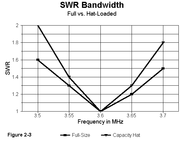
Figure 2-3, using 35VC20 and 35V20 as line generators, compares the hatted short vertical and the full-size vertical with respect to SWR bandwidth. Among the models in this study, only these two exceed a true 200 kHz 2:1 SWR bandwidth.
The series of models 34VC10A through 35VC20A demonstrates the similarity of performance of all hatted verticals having the same main element length and diameter. In common, all models in this series have a 4-wire hat made of #12 lossless wire, as sketched in Figure 2-4. Individual leg lengths are noted in the table. Note that as the diameter of the main element increases, so too does the required leg length in the hat, although the relationship is not linear.

Antenna     Diameter    Each hat         Gain        Feedpoint Impedance
Filename    in inches   wire in feet     in dBi            in R ± jX ohms

35VC10A     1.0"        15.8'            4.947             22.83 + 0.24
35VC15A     1.5"        16.8'            4.945             22.83 - 0.15
35VC20A     2.0"        17.6'            4.943             22.86 - 0.11
Note that the gain decreases (insignificantly in practical terms, but in a numerically noticeable manner) as the element diameter and the leg lengths increase. SWR figures follow:
Antenna     Feed  3.5 MHz     3.55 MHz   3.6 MHz     3.65 MHz    3.7 MHz

35VC10A     SWR   2.0         1.4        1.0         1.4         1.9
            Z     21.0-15.4   21.9-7.6   22.8+0.2    23.8+8.0    24.8+15.7
35VC15A     SWR   2.0         1.4        1.0         1.4         1.8
            Z     21.0-14.8   21.9-7.5   22.8-0.2    23.8+7.2    24.8+14.5
35VC20A     SWR   1.9         1.4        1.0         1.3         1.8
            Z     21.0-14.1   21.9-7.1   22.8-0.1    23.8+6.9    24.8+14.0
Most of the numerical differences in the SWR and feedpoint impedance table figures can be attributed to the slight differentials in reactive offsets at resonance, when expanded over the test frequency range.
Virtually identical performance can be obtained from any hat
configuration. The 23-ohm feedpoint impedance of the hatted
vertical requires only a 2:1 matching section or similar scheme to
permit the antenna to be used with 50-ohm coax. The chief drawback
to this scheme is the mechanical unwieldiness of large hat
assemblies and the likely unavailability of attachment points for
the Marconi wire ends (let alone 4-wire system ends) that would
preserve symmetry. A minor drawback is the fact that these
antennas exhibit a secondary resonance in the range of 13.5 to 13.9
MHz, possibly making them subject to close-by 20 meter
interference. However, hatted short verticals are an option that
should never be far out of mind in monopole design.
Updated 5-12-97. © L. B. Cebik, W4RNL. Data may be used for
personal purposes, but may not be reproduced for publication in print or
any other medium without permission of the author.