 Half-Length 80-Meter Vertical Monopoles:
 35BL10 35BL15 35BL20
35BL10A 35BL15A 35BL20A
35LL1015 35LL1515 35LL2015
Moreover, the feedpoint impedance of the antenna, relative to a full- size monopole, will also be significantly lowered, approaching the feedpoint impedance of the shortened antenna without the base load. Whatever resistive losses may exist in the antenna structure will then occupy a greater proportion of the power fed to the antenna, power that is lost to radiation.
These well-known phenomena are aptly illustrated in models that place lossless inductive loads at the feedpoint to compensate for the reactance.
Antenna   Diameter  Base Load      Gain           Feedpoint Impedance
Filename  in inches in +jX ohms    in dBi         in R ± jX ohms

35BL10    1.0"      287            4.885          7.94 + 0.03
35BL15    1.5"      266            4.886          7.89 + 0.38
35BL20    2.0"      250            4.886          7.85 + 0.06
The gain figures are identical to those of the antenna without the load, since the load inductance has been assigned no loss.
Standard forms of base loading inherently narrow the operating bandwidth of an antenna. Below operating frequency, a higher inductive reactance is needed to bring the antenna to resonance, but an inductor in fact provides less reactance at the lower frequency. The opposite effect occurs above the design center frequency, with the same rapid rise in SWR.
Antenna   Feed 3.5 MHz   3.55 MHz  3.6 MHz   3.65 MHz  3.7 MHz

35BL10    SWR  5.5       2.5       1.0       2.4       4.8
          Z    7.4-14.7  7.7-7.3   7.9+0.0   8.2+7.2   8.5+14.2
35BL15    SWR  4.8       2.2       1.0       2.3       4.6
          Z    7.4-13.3  7.6-6.4   7.9-0.0   8.2+7.0   8.4+13.6
35BL20    SWR  4.7       2.2       1.0       2.2       4.1
          Z    7.4-12.9  7.6-6.3   7.9+0.1   8.1+6.3   8.4+12.5
Although the actual values for reactance for each frequency along the sweep are lower than with some other antennas, for example, the capacity hat examples noted above, they are much higher in relationship to the values of feedpoint resistance, thus resulting in higher SWRs. The other item of note with respect to this model is that two familiar phenomena clearly reveal themselves: the small increase in gain and the increase in operating band width with increases in the main element diameter.
Base-loading using lossless loads can give a misleading impression of potential antenna performance, especially when compared with antenna models whose loading features are physically modeled. Therefore, as a more proper standard of comparison, the inductive base loads were assign an arbitrary Q of 300. This represents the limit of what may be practically possible and may exceed that limit when the physical coil is subject to prolonged atmospheric exposure.
Antenna   Diameter  Base Load      Gain      Feedpoint Impedance
Filename  in inches in R+jX ohms   in dBi         in R ± jX ohms

35BL10A   1.0"      0.96 + 287     4.390          8.90 + 0.03
35BL15A   1.5"      0.89 + 266     4.422          8.78 + 0.38
35BL20A   2.0"      0.84 + 250     4.445          8.69 + 0.06
The coil loss that results in lower gain and a 1-ohm increase in feedpoint impedance, also yields a slightly wider operating bandwidth:
Antenna   Feed 3.5 MHz   3.55 MHz  3.6 MHz   3.65 MHz  3.7 MHz

35BL10A   SWR  4.7       2.3       1.0       2.2       4.2
          Z    8.4-14.7  8.6-7.3   8.9+0.0   9.2+7.2   9.4+14.2
35BL15A   SWR  4.2       2.1       1.0       2.2       4.0
          Z    8.3-13.3  8.5-6.4   8.8-0.0   9.0+7.0   9.3+13.6
35BL20A   SWR  4.1       2.1       1.0       2.0       3.7
          Z    8.2-12.9  8.4-6.3   8.7+0.1   9.0+6.3   9.2+12.5
It is against these numbers, and not against those of a lossless load, that one must compare base linear loading.
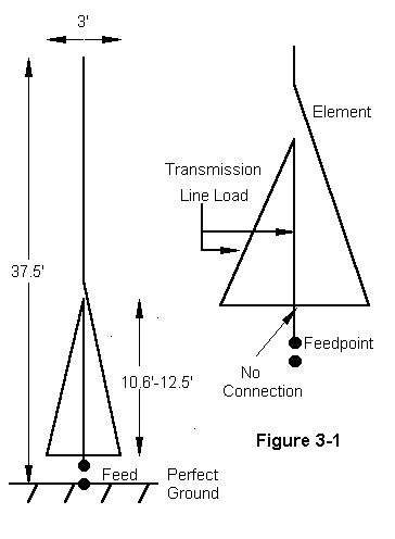
Contemporary antenna construction tends to modify the action of linear loads by using a portion of the main element as one wire of the parallel transmission line. Since this wire ordinarily has a much larger diameter than the pair of supplemental wires making up the other wire of the transmission line section and the initial section of the radiator, radiation in the high current region of the antenna proper is less efficient. To some degree, this inefficiency is compensated for by the imbalance between the lines of the transmission line. further imbalance is introduced by the placement of the transmission lines at differential distances from the radiating segment. Figure 3-1 identifies the structural and electrical elements of a contemporary linearly loaded vertical antenna.

The illustration also reflects the model used to test these antennas. Because all forms of NEC have difficulties with very small angles between wires that join, a model was made of a set of parallel wires with cross wires. The structural main element was modeled at 1, 1.5, and 2 inch diameters. The supplemental wires are spaced 1.5' on either side of the main structural element and are #12 AWG wire. Horizontal connecting wires are also #12 AWG. Adjustments to resonance were made by altering the length of the 3-wire section while maintaining an overall 37.5' length. The gap between structural main element sections was arbitrarily set at 0.05 feet (0.6"). The lower horizontal member is set 0.5' above ground. The height of the gap is thus the length of the linear load plus 0.5'. The results of the modeling for lossless wire are these:
Antenna   Diameter  Linear Load    Gain      Feedpoint Impedance
Filename  in inches length (feet)  in dBi         in R ± jX ohms

35LL1015  1.0"      12.5'          4.891          8.20 + 0.75
35LL1515  1.5"      11.4'          4.891          8.51 + 0.22
35LL2015  2.0"      10.6'          4.892          8.72 + 0.43
Because transmission lines are inherently high Q structures, we should expect base linear loaded models to exhibit a narrow operating bandwidth. The models do not disappoint this expectation.
Antenna   Feed 3.5 MHz   3.55 MHz  3.6 MHz   3.65 MHz  3.7 MHz

35LL1015  SWR  9.7       3.5       1.0       3.8       9.3
          Z    7.5-22.0  7.9-10.8  8.2+0.8   8.6+12.1  9.0+23.4
35LL1515  SWR  8.9       3.3       1.0       3.4       7.9
          Z    7.8-21.6  8.2-10.5  8.5+0.2   8.9+11.2  9.3+21.8
35LL2015  SWR  7.9       3.1       1.0       3.2       7.3
          Z    8.0-20.5  8.4-10.2  8.7+0.4   9.1+10.9  9.5+21.2
The figures for lossless wire, like those of the lumped-constant base- loaded models, are excessively optimistic with respect to gain and excessively pessimistic with respect to operating bandwidth. More realistic would be figures using a real material. For present comparisons, we may use copper as the modeling material, with the understanding that actual losses would be somewhat higher in a real antenna, since a significant portion of the structure would be aluminum.
Antenna   Diameter  Linear Load    Gain      Feedpoint Impedance
Filename  in inches length (feet)  in dBi         in R ± jX ohms

35LL1015  1.0"      12.5'          4.419          9.15 + 0.56
35LL1515  1.5"      11.4'          4.461          9.40 + 0.08
35LL2015  2.0"      10.6'          4.491          9.56 + 0.45
As predicted, the gain figures for base linear loading with copper wire are lower than those for the corresponding base loaded models with lossless loads. However they are comparable and very slightly more favorable than figures for a base loading inductance with a Q of 300. Moreover, the feedpoint impedance increases with main element diameter rather than decreasing, as with lumped-constant base loading. However, this last fact is accounted for by the decreasing size of the linear load and the resultant reduced interaction with the main element.
The results of imbalance among the lines of the transmission line and between those lines and the main radiator show up in several ways. The feedpoint impedances are noticeably higher than with the base-loaded models, although they still fall in the very low range. Second, the length of the linear loads differ somewhat from independently calculated linear loads. Since transmission line stub calculations normally use wires of the same diameter, the independent calculation used #12 AWG wire as a basis and used the base-loading values as targets. Line lengths of 16.3, 15.2, and 14.4 feet were calculated for the three antenna diameters. These lengths are systematically about 3.8 feet longer than the modeled values.
Besides imbalances created by position and wire size, another factor accounts for the length differential. Standard calculations of transmission line stubs do not account for the horizontal connecting wire at the shorted end or for connecting wires to the stub's point of application. For narrow spaced normal transmission lines, these distances are normally an insignificant fraction of the length. In the present case, where wires are space 1.5' apart, these connecting lines are a part of the overall length. Hence, to some degree, not determined in this exercise, the physically modeled horizontal wires must be added to the physical line lengths used in the model. With that in mind, the figures come much closer to agreement.
It may be useful to address briefly the question of treating the linear loads as mid-element loading structures. This mode of visualizing the #12 wire structure is not feasible for several reasons. First, the required mid-element loading reactance is much higher than the base loading reactance, about 1.4 times the base value, although the relationship is not identical for the three main element diameters. Second, the required 36"- wide transmission line stubs would run from nearly 21' for the 1" element to 17.5' for the 2" element. These values are far too long to correlate with the physical models. Third, the feedpoint impedances range from nearly 13.5 ohms for the 1" element to 12.8 ohms for the 2" element. The values differ considerably more from the models by than do the base-loaded values. Consequently, and with due regard to uncalculated variables created by wire-size differentials and wire placement, treating the linear load as a base-loading substitute remains the best model available.
Although transmission lines are inherently high Q structures, they are not lossless. Consequently, real linear loads exhibit a wider operating band width than do models using lossless wire.
Antenna   Feed 3.5 MHz   3.55 MHz  3.6 MHz   3.65 MHz  3.7 MHz

35LL1015  SWR  8.2       3.1       1.0       3.4       7.8
          Z    8.4-22.0  8.8-10.8  9.2+0.6   9.5+12.0  9.9+23.3
35LL1515  SWR  7.6       3.0       1.0       3.0       6.8
          Z    8.7-21.7  9.0-10.6  9.4+0.1   9.8+11.1  10.2+21.8
35LL2015  SWR  6.9       2.8       1.0       2.9       6.5
          Z    8.8-20.5  9.2-10.0  9.6+0.5   10.0+10.9 10.4+21.4

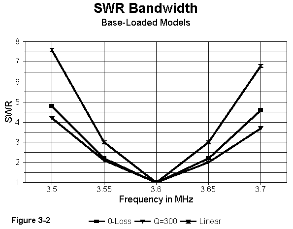
Figure 3-2 compares SWR curves for the 2" diameter models of base loaded (with zero losses and with a Q of 300) and linear loaded models. The figures are more suggestive than precise, since inductors are not physical models and the linear loads have copper wire losses to moderate their values of Q. However, they do suggest that the operating bandwidth of either case, when translated into physical realities with real losses will fall within the range of the curves. Tests with other linear loaded elements shows very little operating bandwidth difference between a well- designed linear load and a high-Q coil.
Any form of base loading, whether in the form of a lumped inductor or
a linear transmission-line inductive reactance results in a low feedpoint
impedance and narrow operating bandwidth, relative to other forms of short
monopole loading. In addition, the base linear loaded models exhibited a
high impedance resonance within the 20-meter band.
Updated 5-12-97. © L. B. Cebik, W4RNL. Data may be used for
personal purposes, but may not be reproduced for publication in print or
any other medium without permission of the author.