 ANTENNAS FROM THE GROUND UP

OCFs are derived from the Windom antenna, a 1929 concoction using a single- wire feed attached to the antenna element at what was believed to be the 600-ohm point. The single wire feedline was presumed to have an impedance of 600 ohms against ground.
The magic dimensions of the OCF vary from writer to writer. The dimension L is almost universally given as the ballpark dipole formula

Windom gives the offset by the formula

Later developments that replaced the single-wire feedline with a normal two-wire feedline preferred somewhat different dimensions. The ARRL Antenna Book uses the formula

Carr gives the figure as 0.174 (Practical Antenna Handbook). What these numbers have in common is the belief that the feedpoint is the 300-ohm point along the antenna element. Some builders wish to insert a 4:1 or a 6:1 balun at this point and feed the antenna with 50-ohm coaxial cable.
The antenna is claimed to provide a good match under these conditions to coax on the fundamental and most even harmonics. An 80-meter antenna would thus match well on 40, 20, and 10, while a 40-meter antenna would match well on 20 and 10 meters.
A more recent version of the antenna cut for 40 meters uses a different ratio:

This placement is believed to hit the 100-ohm point on the antenna wire, where a 2:1 balun will reduce the impedance to 50 ohms for coaxial feed on the fundamental and even harmonics. This version of the OCF assumes that there is RF on the outside of the coax forming a supplemental vertical radiator of about 10' length on the 40-meter model. The claims made for this technique are (1) an increase in gain off the ends of the antenna and (2) a lower angle of maximum radiation.
We could go on reciting claims about the OCF, but these are enough to give a flavor of the reported benefits of the design. I have even seen claims that it outperforms a beam. On the down side are experiences by many QRO users of RF in the shack. In addition, many builders have seemed unable to achieve the nice clean 50-ohm matches claimed by some Windom kit sellers.
So we have a pair of questions: a. How does an OCF work? And b. Are any of the claims about OCFs true enough to be reliable?
The OCF does work! Before we tackle the claims made about the OCF antenna, let's start by saying that it will work, but not significantly better than a dipole of the same length. Hence, the best installation for an OCF is a matter of convenience. If feeding the antenna up to a ratio of D1/D2 of 1/3 is more convenient to the shack, then do so. However, use parallel feedline and an ATU for all-band matching purposes, omitting all baluns (even the one inside the tuner.)
To prevent RF from affecting other shack equipment, do one of the following things: a. At the entry to the house or shack, install a W2DU choke and convert to coax to the ATU; or b. Between the ATU and the transceiver, install a line isolator (another name for the W2DU choke) at the ATU end of the cable.
By the time we complete our analysis of the claims made for the OCF, you will understand why the antenna is not much different than a center-fed dipole, and certainly not significantly better.
How long to make it and where to feed it: As you move the feedpoint of a 1/2 wavelength wire from the center toward the end, the impedance increases while remaining essentially resistive with no reactive component. Hence, somewhere along the wire, there is a 100-ohm feedpoint, a 300-ohm feedpoint, and a 450-ohm feedpoint. However, we have learned that the feedpoint impedance of a resonant center-fed dipole changes with the height of the antenna. Moreover, the resonant length of the antenna changes with the height. Hence, the various desirable feedpoints are not at the same place on antennas of different heights.
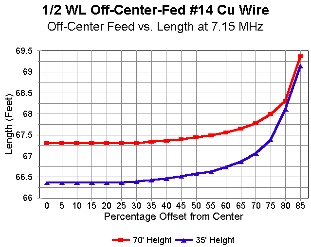
The first graph shows the length of two 40-meter OCFs, one at 35' and the other at 70' (1/4 and 1/2 wavelength up, respectively). The percentages are the ratio of D3 to 1/2L, in other words, the percentage of the distance outward from the center for the feedpoint. Not only are the lengths of the two antennas different, but as well, the resonant length of the antenna grows longer as the feedpoint is moved outward, especially after the 25% to 30% mark. In no case does the antenna correspond to the overall length overall length given in equation (1).

The second graph gives an overview of what happens to the feedpoint impedance of the antenna as that point is moved outward from center. Note that as the impedance passes through 300 ohms, the curve grows steeper rapidly, making the process of setting a 300-ohm feedpoint tricky at best. It is much easier to hit the 100-ohm feedpoint, but not quite as easy as this compressed graph suggests.
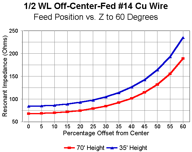
The third graph decompresses the second by cutting off the steepest part of the curve. It reveals the quite different feedpoint impedances for the two antennas as the feedpoint moves away from center.
Remember that the NEC models from which these graphs are derived presume level, uncluttered terrain. Messy, uneven terrain will throw additional variables into the mix. Finding the exact feedpoint positions to match any given feedline will be challenging at best.
Moreover, the feedpoint positions are fairly narrow-banded. The illusion of broadband performance is usually achieved by the use of lossy balun designs. Although QRO may have power to spare for such purposes, QRP operations rarely have that luxury.
What About the Radiation Pattern? An OCF at its fundamental frequency performs similarly to a center-fed dipole of the same length. A center-fed half-wavelength wire antenna cut for 7.15 MHz (about 67.3' long) has a maximum gain of about 7.6 dBi at 70' up, with an elevation angle of maximum radiation of 27 degrees above the flat, uncluttered terrain assumed by NEC programs. This is the standard against which to measure the performance of OCF antennas.
If we first assume that all radiation occurs in the antenna element and none in the feedline, then we discover that the gain of an OCF for the same frequency at the same height is 7.6 dBi with a take-off angle of 27 degrees. Figure 5 shows the azimuth pattern.
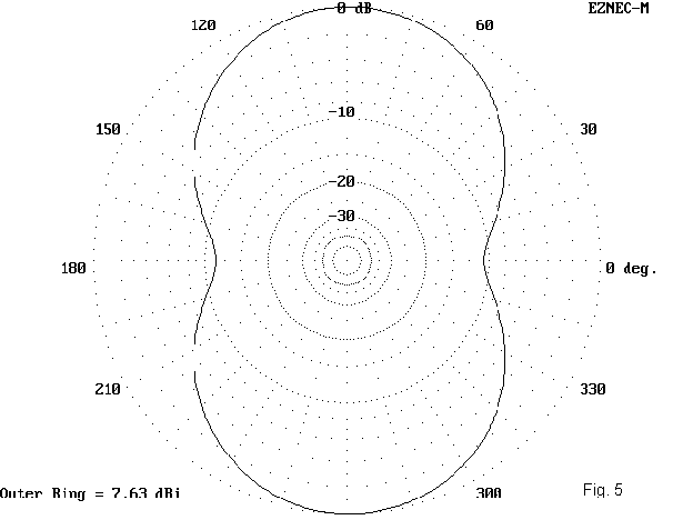
This pattern is taken from the 300-ohm feedpoint position, which (at this height) indicates a length of 10.4' on the short side of the feedloint and 57.35' on the long side. In this configuration, the asymmetry is barely noticeable, as the angle of maximum radiation bends by a mere 2 degrees from that of a dipole and the long end of the antenna shows about 2 dBi less indentation than the short side.
We might assume that this pattern holds for the version of the OCF antenna that uses a 4:1 or a 6:1 balun at the antenna feedpoint. Of course, we must also assume that the balun is lossless and that it effects a very high degree of isolation between the antenna wire and the feedline. If the balun alone does not achieve the isolation, we might also insert a W2DU choke on the coax side of the balun.
Next, let's assume that the feedline radiates. Most treatments of feedline radiation in modeling have been oversimplified to the point of presenting highly misleading results. The key mistake has been to assume that there is a lossless division of current at the junction of the antenna and the radiating vertical wire. The second assumption is that the feedpoint impedance remains essentially the same as when the antenna alone does the radiating. Neither assumption is necessarily true.
Moreover, modeling transmission line physically also presents problems that lead many modelers to improperly oversimplify their models. 450-ohm line is easier to model, since it uses wider spacing. 300-ohm line requires closer spacing. Since NEC-2 is most accurate when all wires are of the same diameter, and since physical models of transmission lines will have a velocity factor of 1, the physical model will always be only an approximation of the use of actual feedlines.
Nonetheless, modeled feedlines checked for accuracy against a center-fed dipole can determine certain facts and trends that apply to the OCF. First among those facts is that when the feedline radiates, the impedance at the junction of the antenna element and the feedline is no longer what is was for a nonradiating feedline. The feedline is part of the antenna. If we use a parallel feedline from the antenna element to some point below it, the radiation that results from this line is not due to the entire current on the line, but only from that part of it which is not balanced. Failure to note this situation has resulted in significant overestimates of the degree to which feedlines radiate and to the contribution of the feedline to the overall antenna pattern.
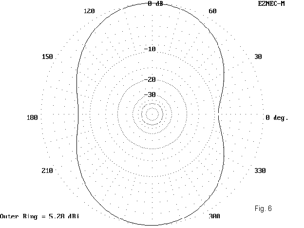
Figure 6 shows the azimuth pattern of our 7.15 MHz OCF with 35' of 300-ohm parallel feedline. With this length of radiating parallel feedline, the gain of the maximum lobes drops to about 5.9 dBi. The lost gain goes into the radiation off the ends, which is increased a few dB on each side of the pattern. The overall performance in this mode is essentially that of a basic dipole.
Terrain unevenness and ground clutter will likely make a much larger difference in the performance of individual OCFs than the radiation from the feedline.
Let us assume that instead of a length of parallel feedline, a single wire runs from one side of the antenna straight down for 35' or so. This is the assumption made by many modelers for the situation of radiating coaxial cable shields. Although this assumption may be closer to correct for center-fed antennas where there is a direct connection between the cable shield and one side of the antenna, the assumption is dubious in the case of OCFs because builders ordinarily insert baluns or ununs at the antenna element junction to effect an impedance transformation.
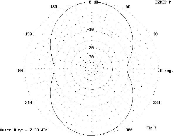
Figure 7 shows the azimuth pattern of an antenna meeting our assumptions. The gain of the main lobes is up to 7.3 dBi, but the radiation off the ends is down compared to the radiating parallel feedline. However, the differential among all three of our antennas is operationally insignificant.
Even lengthening the feedline to a half wavelength does not alter the pattern very significantly. Under these same conditions, again assuming a perfect connection to the antenna element, one might achieve a one-sided puckered peanut pattern, but with a maximum gain of only 5.7 dBi and with only a 1 degree reduction in the angle of maximum radiation.
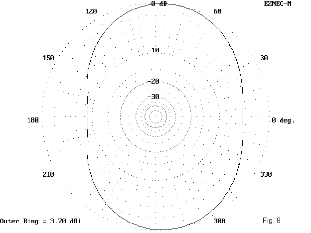
Figure 8 shows what happens if we increase the radiating parallel feedline to a full half wavelength. The gain drops to about 3.7 dBi, with a take- off angle of 24 degrees. The pattern is a significant oval (instead of a peanut): it yields a somewhat stronger signal off the ends--but no more than for an inverted Vee of moderate slope at the same peak height.
At the fundamental frequency of an OCF antenna, performance is thus at best
similar to that of a center-fed 1/2 wavelength dipole and at worst about that of an
inverted Vee. Intentionally striving for a radiating feedline achieves
very little, while accepting a feedline that radiates harms little (if
adequately isolated from equipment in the shack). Stay tuned; there's more
to come.
Updated 1-25-98. © L. B. Cebik, W4RNL. Data may be used for personal purposes, but may not be reproduced for publication in print or any other medium without permission of the author.