 ANTENNAS FROM THE GROUND UP
I do not intend to resolve the controversy. Instead, let's try to understand some of what makes the controversy a hamfest favorite. First of all, the polarization of signals is only indirectly related to the dispute. The ionosphere skews most polarized signals most of the time, so that everyone receives a mixed bag--most of the time.
Polarization does influence the far field antenna pattern. And that does make a difference. So that is what we shall probe here. We shall confine ourselves to elevation patterns of various antennas, because that will give us a good picture of how far we can throw a signal and catch one coming back.
Second, since our space is limited, I shall put all of our antennas on 7.15 MHz. However, everything said applies to each of our low bands if you translate all heights into fractions of a wavelength.
The Horizontal Tradition: Let's start with the 1/2 wl dipole and use it as a standard for comparisons. For the most part, we are interested in various angles of radiation: a. the elevation angle of maximum radiation (take-off angle) and b. certain specific elevation angles for comparing long-distance performance. We can chart the take-off angle at several heights with intervals of 1/8 wl, (which is about 17.2' at 7.15 MHz).
Ht wl       Ht feet        T-O Angle (deg)
0.125       17.2           90
0.25        34.4           61
0.375       51.6           38
0.5         68.8           28
0.625       86.0           22
0.75        103.2          19
0.875       120.4          16
1.0         137.6          14
Most ham antennas are 1/2 wl or lower on 160-30 meters. Hence, the dipole has a high angle of radiation. The elevation pattern for the dipole at 1/4 wl up looks like Figure 1.
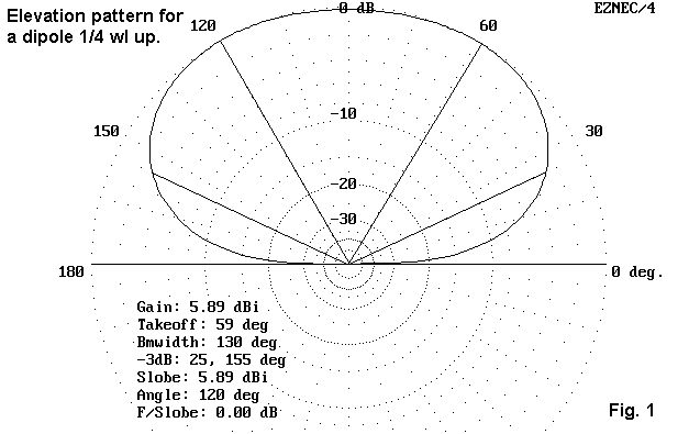
Although the antenna is quite satisfactory for high-angle, shorter skip paths, the gain at an elevation angle of 20° is about 1.5 dBi. Obviously, the received signals and noise will be dominated by sources closer in.
We can improve on this situation by building horizontal antennas with lower take-off angles. One such antenna is the wire Yagi. Using #14 wire, a driven element about 66' long and a reflector about 70' long, with about 20' spacing, will give us some improvement in both take-off angle and in gain in the desire direction.
Ht wl                   Ht feet                 T-O Angle (deg)
0.125                   17.2                    58
0.25                    34.4                    45
0.375                   51.6                    34
0.5                     68.8                    27
0.625                   86.0                    22
0.75                    103.2                   18
0.875                   120.4                   16
1.0                     137.6                   14
Note that the improvement in elevation angle is mostly at the lowest heights. Above a half-wavelength, the take-off angle closely matches that of the dipole. The 2-element Yagi elevation pattern at a 1/4 wl height looks like Figure 2.

The Yagi exhibits about 3 dB more gain than the dipole at the angle of maximum radiation. At an elevation angle of 20°, the gain is about 5.3 dBi, nearly 4 dB better than the simple dipole. Nevertheless, like the dipole, the received signal and noise is dominated by high angle radiation.
A unidirectional beam is not the only way to achieve better performance at lower angles. Consider a single, vertically oriented, quad loop about 36' on a side. We shall feed our model at the bottom for a horizontally polarized pattern. This antenna will require high support, but that high wire also provides the antenna with a lower overall elevation angle of radiation at every height. Indeed, with respect to take-off angles, the dipole-equivalent height of a quad is about 2/3rds the way up a quad. Here is the table of take-off angles for the quad loop.
Ht wl                   Ht feet                 T-O Angle (deg)
0.125                   17.2                    43
0.25                    34.4                    32
0.375                   51.6                    26
0.5                     68.8                    21
0.625                   86.0                    18
0.75                    103.2                   15
0.875                   120.4                   14
1.0                     137.6                   12
The elevation pattern for the loop with the bottom wire 1/4 wl up appears in Figure 3.
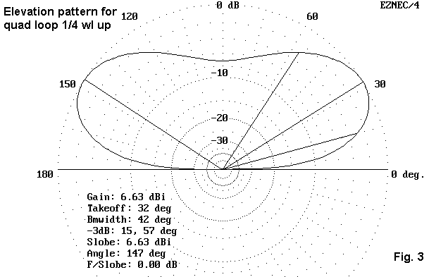
Although the quad loop cannot match the gain of the Yagi at their respective angles of maximum radiation, the quad has a gain of 5.3 dBi at an elevation angle of 20°. Moreover, if you inspect the pattern of the quad loop, you will see that it devotes less pattern space to the highest angles of radiation found in the dipole or Yagi patterns. The result is that lower angle signals will be proportionally stronger relative to higher angle signals, making reception easier for the operator.
There are some very good reasons to avoid horizontally oriented 1 wl loops of any shape (triangle, square, hexagon, etc.) All such loops are designed for radiation broadside to the flat of the antenna. When laid out horizontally, they try their best to radiate upward. At very low heights (up to 1/4 wl), they display take-off angles well above those of a dipole. Between 5/8 wl and 1 wl, they display a center bulge straight upward that is stronger than the low angle radiation lobes. In the table, the main lobe is shown, followed by a secondary lobe angle if the main lobe is straight up.
Ht wl           Ht feet         T-O Angle (deg)
0.125           17.2            89
0.25            34.4            86
0.375           51.6            44
0.5             68.8            30
0.625           86.0            23
0.75            103.2           84 (19)
0.875           120.4           59 (17)
1.0             137.6           48 (15)

Figure 4 shows the elevation plot of a hex 1 wl loop at 1/4 wl height for comparison with the other antennas.
Because it sometimes difficult to grasp the full import of antenna plots when each is set to touch the outer ring, Figure 5 compares in scale the elevation patterns of the dipole, the Yagi, and the vertically oriented quad loop, all at 1/4 wl height, with the quad's lower wire at that height. The figure is larger to make the comparison easier.

Note especially the very comparable low angle radiation gains for both the quad and the Yagi. However, notice the amount of high-angle radiation in the Yagi pattern.
The Vertical Mystique: Low-band DXers claim that they can work more DX on a vertical than a horizontal antenna. This assumes, of course, that the DXer in question does not have access to 200' towers and unlimited funds for quads, Yagis, and log periodics. Does the claim make any sense, and if so, why?
First, let's understand what we mean by a vertical antenna. They come in three general types. First is the quarter-wave ground plane vertical, either ground-mounted or elevated. Related to this antenna are phased arrays of verticals and the 5/8 wl vertical. Second comes the vertical dipole and any antenna that we might derive from a dipole, such as a Yagi. These antennas require no ground plane, since both poles of the antenna are physically included in the design. Third is a class of wire antennas that include the equilateral delta (fed 25% up one leg), the right-angle delta (fed 12% up one leg), and the half square. All of these antennas are closed loop antennas (with the half-square being harmlessly opened at what would have been the high voltage apex). This last antenna is usually mounted with its horizontal wire a the top and the vertical elements hanging downward, while the usual arrangement for the deltas is to run the horizontal wire at the bottom and let the apex be at the top.
A more correct way to view the feedpoints of these three antennas is to see them as being 1/4 wl from the apex or open end. All require a full wavelength of wire, with the centermost 1/2 wl of wire constituting a phasing section whose radiation cancels itself, leaving only the radiation from the most vertical quarter-wavelength sections. The result is predominantly vertical polarization; more importantly, the patterns take on many of the characteristics of the other classes of vertical antennas. Note, however, that moving the feedpoint to other parts of the antenna radically changes the antenna's pattern and performance. Fed at the center, they are not verticals.
Because the ground plane vertical has so many variables that affect its efficiency, let's use the vertical dipole as our standard. Even bypassing the ground-plane antenna, it is difficult to draw exact comparisons among vertically polarized antennas. Verticals do not share a common horizontal plane that we can call the antenna height. However, Figure 6 shows the elevation plot of a vertical dipole 10' off the ground at its lower end. Its feedpoint is about 44' up and the highest end is about 78' up.

The angle of maximum radiation is 16° and the gain is only 0.24 dBi. However, notice the relative absence of high angle radiation. We shall say more about this before we are finished.
The right-angle delta is perhaps the more effective of the two deltas, with a feedpoint impedance near 50 ohms. It takes more horizontal space, but less vertical space than the equilateral delta. And it has more gain off the broadside of the antenna. Figure 7 shows the elevation patterns of a right-angle delta with the base at 30' At this height, the take-off angle is 17° and the gain is 2.0 dBi. Lowering the base of the antenna to 20' decreases the gain to 1.9 dBi and raises the take-off angle to 20°.

Among the wire verticals, the half square has the highest gain, in part because its normal low-band orientation places the high current feedpoint at the uppermost part of the antenna structure. Like the right-angle delta, the corner-fed half square has a feedpoint impedance that closely matches coax. Figure 8 shows the elevation pattern of a half square whose lowest point is 20'. I recommend you keep the half square at this level (slightly lower does not harm performance significantly). The pattern shows a slight bulge at the 60° elevation point, and this bulge grows into a significant lobe as the antenna is further elevated.
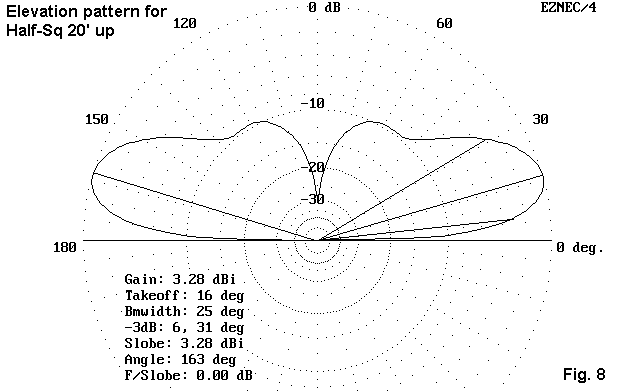
Notice that the gain of the half square is about 3.3 dBi, a significant improvement over both the dipole and the right-angle delta. The cost is a somewhat narrower oval azimuth pattern at the take-off angle of 16° (the lowest of the three verticals modeled here).

To get a better grasp of how much the high angle radiation is reduced by these verticals, Figure 9 shows a composite of the horizontal dipole, the vertical dipole, and the half square, all at the heights specified earlier. Since there is no planar standard, the comparison is only suggestive and not authoritative.
Notice that the dipole has the highest gain, but at very high radiation angles. At the lowest angles, the verticals have higher gain, plus a very dramatic reduction of high-angle radiation.
Consider the high angle radiation pattern in terms of reception. For the dipole, all of the QRM, QRN, and background noise of the closer skip distances dominates reception, lowering the signal-to-noise ratio of any low angle DX that might otherwise be heard. The verticals, despite their lower maximum gains, act as natural filters, being less sensitive by at least 2 S-units to high-angle radiation. At the lowest (DX) elevation angles, the verticals are competitive in strength with the dipole. Little wonder that low-budget Dxers like them.
So What's A Poor Ham To Do? First, think about what kind of operating you
like to do and choose the class of antenna that is likely to perform best
for that purpose. Second, figure out the limits of what you can erect and
maintain. Then go to work on your antenna. Ideally, of course, it is nice
to have two antennas, one for shorter skip, one for DX--and a switch. With
proper planning and a lot of work, dreams can come true.
Updated 12-15-97. © L. B. Cebik, W4RNL. Data may be used for personal purposes, but may not be reproduced for publication in print or any other medium without permission of the author.