 ANTENNAS FROM THE GROUND UP

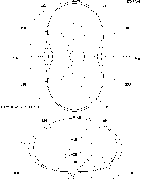
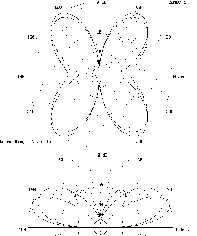
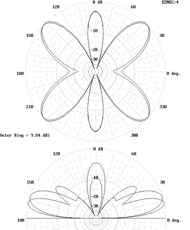
It is important to understand that the pattern of lobes and nulls varies with each band. This information is useful for orienting the antenna and for properly anticipating performance. The precise length of the antenna between 130' and 140' will have little effect on the individual band patterns.
Changes of length will have a more profound effect upon the feedpoint impedance, as will changes of height. In contrast, changes of wire diameter between AWG #18 and #10 will have little noticeable effect.
The pages to follow are designed to allow the antenna builder to have some reasonable expectations both for antenna patterns and for impedances presented to the ATU by the antenna and its feedline. Each column in the following pages is devoted to the performance of the antenna on one of the HF bands from 80 to 10 meters. For each band there is a composite pattern plot and a pair of tables.
The patterns show NEC-2 plots of the antenna at heights of 35' and 50'. The 35' pattern is always the inner or weaker of the two patterns. If the angle of maximum radiation is greater than 45°, then the azimuth pattern is taken at an elevation angle of 45°. If the angle of maximum radiation is less than 45°, then the take-off angle is used. The elevation patterns are taken at the azimuth angle of the strongest lobe. Therefore, interpreting the patterns requires that you consider azimuth and elevation together.
The tables list, in highly rounded numbers, the impedance presented along parallel transmission lines every 20° (electrical) for a half wavelength. Standard 450-ohm (Velocity Factor = 0.95) and 300-ohm (VF = 0.80) lines are given. Note that each electrical degree represents a different length in feet and meters for each band and line type. Values are for lossless lines from the 50' high antenna.
Since impedance values repeat themselves every 180° along a feedline, you may estimate (very broadly at best) the impedance presented to your ATU. Divide the length in feet or meters of your transmission line by the length of a half-wavelength (180°) of the same line. Ignore the integer and multiply the fraction of a half wavelength by 180 to arrive at the value in degrees to check against the applicable table.

80 meters: 3.6 MHz
AZ plots:   Elevation angles = 45°
EL plots:   Azimuth angles = 90°

Feedpoint Z (R ± jX): 75 + 55 ohms

TL = 450 ohm; VF = .95
Deg  Feet 	Meters  R ± jX (ohms)
 0    0   	0   	75 + 55
20   14.4 	4.4  	95 + 220
40   28.8 	8.8  	155 + 455
60   43.3 	13.2 	420 + 890
80   57.7 	17.6 	2450 + 770
100  72.1 	22.0 	680 - 1107
120  86.5 	26.4 	200 - 555
140  101.0      30.8 	105- 280
160  115.4      35.2 	80 - 100
180  129.8      39.6 	75 + 55

TL = 300 ohm; VF = .80
Deg  Feet 	Meters  R ± jX (ohms)
 0    0    	0   	75 + 55
20   12.1 	3.7  	95 + 165
40   24.3 	7.4  	170 + 315
60   36.4 	11.1 	450 + 540
80   48.6 	14.8 	1220 - 55
100  60.7 	18.5 	415 - 525
120  72.9 	22.2 	160 - 305
140  85.0 	25.9 	95 - 155
160  97.1 	29.6 	75 - 45
180  109.3      33.3 	75 + 55

40 meters: 7.15 MHz
AZ plots: El. Angle = 45° @ 35';
                      39° @ 50'
EL plots: Az. Angles = 90°

Feedpoint Z (R ± jX): 4760 - 1270 ohms

TL = 450 ohms; VF = .95
Deg  Feet 	Meters  R ± jX (ohms)
 0    0    	0   	4760 - 1270
20   7.3  	2.2  	285 - 1085
40   14.5 	4.4  	90 - 500
60   21.8 	6.6  	50 - 245
80   29.0 	8.9  	40 - 70
100  36.3 	11.1 	40 + 90
120  43.6 	13.3 	55 + 270
140  50.8 	15.5 	100 + 550
160  58.1 	17.7 	365 + 1240
180  65.3 	19.9 	4760 - 1270

TL = 300 ohms; VF = .80
Deg  Feet 	Meters  R ± jX (ohms)
 0    0    	0   	4760 - 1270
20   6.1  	1.9  	135 - 765
40   12.2 	3.7  	40 - 345
60   18.3 	5.6  	25 - 165
80   24.5 	7.5  	20 - 50
100  30.6 	9.3  	18.3 + 60
120  36.7 	11.2 	25 + 180
140  42.8 	13.0 	45 + 365
160  48.9 	14.9 	160 + 840
180  55.0 	16.8    4760 - 1270

30 meters: 10.125 MHz
AZ plots: El. Angle = 39° @ 35';
                      27° @ 50'
EL plots: Az. Angles = 90°

Feedpoint Z (R ± jX): 95 - 330 ohms

TL = 450 ohm; VF = .95
Deg  Feet 	Meters  R ± jX (ohms)
 0    0    	0   	95 - 330
20   5.1  	1.6  	65 - 135
40   10.3 	3.1  	60 + 20
60   15.4 	4.7  	70 + 185
80   20.5 	6.3  	110 + 405
100  25.6 	7.8  	270 + 805
120  30.8 	9.4  	1805 + 1645
140  35.9 	10.9 	910 - 1445
160  41.0 	12.5 	195 - 655
180  46.1 	14.1 	95 - 330

TL = 300 ohms; VF = .80
Deg  Feet 	Meters  R ± jX (ohms)
 0    0    	0   	95 - 330
20   4.3  	1.3  	55 - 165
40   8.6  	2.6  	40 - 45
60   13.0 	4.0  	40 + 55
80   17.3 	5.3  	55 + 175
100  21.6 	6.6  	100 + 350
120  25.9 	7.9  	330 + 730
140  30.2 	9.2  	2160 - 230
160  34.5 	10.5 	290 - 685
180  38.9 	11.8 	95 - 330

20 meters: 14.15 MHz
AZ plots: El. Angle = 27° @ 35';
                      19° @ 50'
EL plots: Az. Angles = 52° @ 35'
                       55° @ 50'

Feedpoint Z (R ± jX): 4270 - 1005 ohms

TL = 450 ohm; VF = .95
Deg  Feet 	Meters  R ± jX (ohms)
 0    0    	0   	4270 - 1005
20   3.8  	1.1  	405 - 1215
40   7.3  	2.2  	115 - 550
60   11.0 	3.4  	60 - 270
80   14.7 	4.5  	45 - 90
100  18.3 	5.6  	45 + 70
120  22.0 	6.7  	60 + 240
140  25.7 	7.8  	100 + 500
160  29.4 	9.0  	320 + 1070
180  33.0 	10.1 	4270 + 1005

TL = 300 ohm; VF = .80
Deg  Feet 	Meters  R ± jX (ohms)
 0    0    	0   	4270 - 1005
20   3.1  	0.9  	180 - 830
40   6.2  	1.9  	50 - 365
60   9.3  	2.8  	25 - 180
80   12.4 	3.8  	20 - 60
100  15.5 	4.7  	20 + 50
120  18.5 	5.7  	25 + 165
140  21.6 	6.6  	45 + 345
160  24.7 	7.5  	150 + 760
180  27.8 	8.5  	4270 - 1005

17 meters: 18.1 MHz
AZ plots: El. Angle = 19° @ 35';
                      14° @ 50'
EL plots: Az. Angles = 29° @ 35'
                       30° @ 50'

Feedpoint Z (R ± jX): 125 + 5 ohms

TL = 450 ohm; VF = .95
Deg  Feet 	Meters  R ± jX (ohms)
 0    0    	0   	125 + 5
20   2.9  	0.9  	145 + 155
40   5.7  	1.8  	205 + 335
60   8.6  	2.6  	420 + 585
80   11.5 	3.5  	1210 + 645
100  14.3 	4.4  	1155 - 670
120  17.2 	5.2  	400 - 575
140  20.1 	6.1  	205 - 325
160  22.9 	7.0  	140 - 145
180  25.8 	7.9  	125 + 5

TL = 300 ohm; VF = .80
Deg  Feet 	Meters  R ± jX (ohms)
 0    0    	0   	125 + 5
20   2.4  	0.7  	140 + 90
40   4.8  	1.5  	195 + 185
60   7.3  	2.2  	340 + 280
80   9.7  	2.9  	635 + 195
100  12.1 	3.7  	610 - 215
120  14.5 	4.4  	320 - 275
140  16.9 	5.2  	190 - 180
160  19.3 	5.9  	140 - 85
180  21.7 	6.6  	125 + 5

15 meters: 21.15 MHz
AZ plots: El. Angle = 18° @ 35';
                      13° @ 50'
EL plots: Az. Angles = 41° @ 35'
                       43° @ 50'

Feedpoint Z (R ± jX): 2330 + 1435 ohms

TL = 450 ohms; VF = .95
Deg  Feet 	Meters  R ± jX (ohms)
 0    0    	0   	2330 + 1435
20   2.5  	0.8  	735 - 1300
40   4.9  	1.5  	185 - 605
60   7.4  	2.2  	90 - 305
80   9.8  	3.0  	65 - 120
100  12.3 	3.7  	65 + 40
120  14.7 	4.5  	75 + 205
140  17.2 	5.2  	125 + 435
160  19.6 	6.0  	320 + 870
180  22.1 	6.7  	2330 + 1435

TL = 300 ohm; VF = .80
Deg  Feet 	Meters  R ± jX (ohms)
 0    0   	 0   	2330 + 1435
20   2.1  	0.6  	310 - 905
40   4.1  	1.3  	75 - 395
60   6.2  	1.9  	40 - 195
80   8.3  	2.5  	30 - 70
100  10.3 	3.2  	30 + 35
120  12.4 	3.8  	35 + 150
140  14.5 	4.4  	60 + 310
160  16.5 	5.0  	170 + 660
180  18.6 	5.7  	2330 + 1435

12 meters: 24.95 MHz
AZ plots: El. Angle = 14° @ 35';
                      10° @ 50'
EL plots: Az. Angles = 23° @ 35'
                       24° @ 50'

Feedpoint Z (R ± jX): 130 - 180 ohms

TL = 450 ohm; VF = .95
Deg  Feet 	Meters  R ± jX (ohms)
 0    0   	 0   	130 - 180
20   2.1  	0.6  	110 - 25
40   4.2  	1.3  	120 + 130
60   6.2  	1.9  	170 + 305
80   8.3  	2.5  	325 + 565
100  10.4 	3.2  	1020 + 855
120  12.5 	3.8  	1490 - 675
140  14.6 	4.4  	440 - 670
160  16.6 	5.1  	200 - 375
180  18.7 	5.7  	130 - 180

TL = 300 ohm; VF = .80
Deg  Feet 	Meters  R ± jX (ohms)
 0    0   	 0   	130 - 180
20   1.8  	0.5  	100 - 70
40   3.5  	1.1  	95 + 25
60   5.3  	1.6  	110 + 125
80   7.0  	2.1  	170 + 250
100  8.8  	2.7  	370 + 410
120  10.5 	3.2  	920 + 205
140  12.3 	3.7  	575 - 440
160  14.0 	4.3  	230 - 320
180  15.8 	4.8  	130 - 180

10 meters: 28.5 MHz
AZ plots: El. Angle = 13° @ 35';
                      10° @ 50'
EL plots: Az. Angles = 36° @ 35'
                       37° @ 50'

Feedpoint Z (R ± jX): 2070 + 1225 ohms

TL = 450 ohms; VF = .95
Deg  Feet 	Meters  R ± jX (ohms)
 0    0   	 0   	2070 + 1225
20   1.8  	0.6  	835 - 1230
40   3.6  	1.1  	215 - 605
60   5.5  	1.7  	105 - 310
80   7.3  	2.2  	75 - 120
100  9.1  	2.8  	70 + 35
120  10.9 	3.3  	85 + 200
140  12.8 	3.9  	135 + 420
160  14.6 	4.4  	345 + 825
180  16.4 	5.0  	2070 + 1225

TL = 300 ohms; VF = .80
Deg  Feet 	Meters  R ± jX (ohms)
 0    0   	 0   	2070 + 1225
20   1.5  	0.5  	360 - 895
40   3.1  	0.9  	90 - 395
60   4.6  	1.4  	45 - 195
80   6.1  	1.9  	35 - 70
100  7.7  	2.3  	30 + 35
120  9.2  	2.8  	40 + 145
140  10.7 	3.3  	65 + 305
160  12.3 	3.7  	190 + 640
180  13.8 	4.2  	2070 + 1225
Updated 7-1-97. © L. B. Cebik, W4RNL. Data may be used for personal purposes, but may not be reproduced for publication in print or any other medium without permission of the author.