 ANTENNAS FROM THE GROUND UP
First, you have to like your computer. Second, although there are some basic modeling cores for MAC, modeling is a PC business, especially if you want to use one of the commercial versions. Third, you have to learn how to ask the modeling program good questions and read its answer intelligently. Although I cannot make you like your computer, I can tell you where to find software and how to get started in using it wisely.
Even if you do not intend to buy or download a modeling program, you should continue reading. When you are done, you will at least have a better grasp of what all those antenna plots and graphs in the magazine articles are trying to tell you.
However, when most folks speak of antenna modeling these days, they are referring to the Numerical Electromagnetics Code, either in its FORTRAN version (NEC) or its offshoot BASIC version (MININEC). These programs are very powerful "method of moments" calculation machines that, within limits, can produce a lot of accurate information about antennas.
Both NEC-2 and MININEC are public domain programs, so you can download them for free. However, you have to design your own user interface to get information about your antenna in and get calculation results out. Like this:

Figure 1 told me that I cut the 40-meter dipole model too long, so I pruned a number rather than a piece of wire.
Both NEC and MININEC have limitations. NEC-2 cannot handle wires of dissimilar diameters well, but it can deal with antennas close to ground. MININEC is limited to antennas above 0.2 wavelengths above ground and requires special techniques to handle wires that meet at angles. Both have their place, but for wire antennas in the 160-30 meter region, I recommend NEC.
There are three commercial versions of NEC-2 available to hams for under $90. These are
EZNEC, by Roy Lewallen, W7EL, P.O. Box 6658, Beaverton, OR 97007. This DOS program ($89) has a "friendly" user interface by most reports and a 500-segment limit for antenna size.
NEC/Wires by Brian Beezley, K6STI, 3532 Kinda Vista, San Marcos, CA 92069. This DOS program ($70) uses a different input interface that allows formulas; also with a similar segment limit.
NEC-Win Basic by Paragon Technologies, 3006 Research Drive, State College, PA 16803. This is the only Windows version of NEC ($75) and uses a spreadsheet style input system.
Both EZNEC and NEC-Win have "big brothers" for virtually unlimited antenna sizes, and NEC-Win Pro has added graphics capabilities. However, prices are considerably higher.
All three programs have been designed or tested by hams. I use versions of all three from time to time, along with the MININEC versions of each (ELNEC from W7EL and AO from K6STI, along with NEC4WIN from Orion in Canada and MININEC for Windows from MININEC creators Rockway and Logan).
First, you create a physical model of the antenna of interest, laying out wires on an X, Y, Z coordinate system, and specifying wire size and material, ground conditions, and other information needed for the analysis. Then the program provides you with (as a start) complete far field information (available graphically or in tables), feedpoint impedance and related data, antenna current levels, and more.
The numerical data, such as feedpoint impedance and SWR relative to 50 ohms, is easy to interpret. Antenna patterns require a little more effort.
Let's start in free space, that spherical volume in žouter spacež free of all conductive obstructions. Let's place a dipole there and look at its 3-D pattern. It looks like Figure 2, where the wire-line is a highly magnified orienting guide to the antenna position. Since this is a "far-field" pattern, the actual antenna would be too minuscule to see.
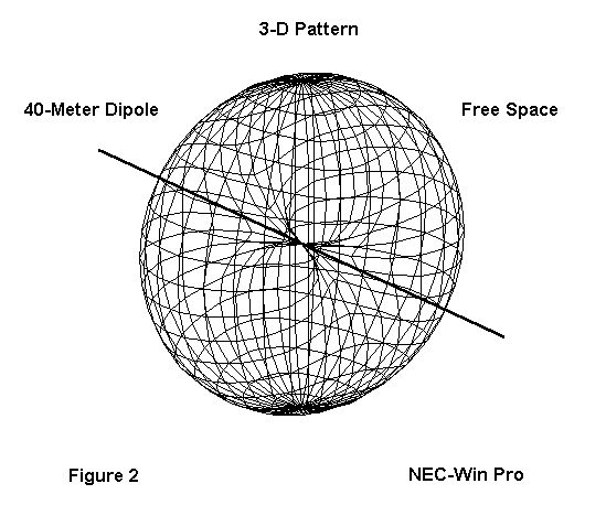
An azimuth pattern is one tracing a horizontal circle around the antenna pattern. We take azimuth patterns at some specified elevation angle. For free space, the angle is typically (but not absolutely always) 0° elevation. Mentally cutting Figure 2 on the flat, which is almost from the bottom left corner to the top right corner, we get the following azimuth pattern:
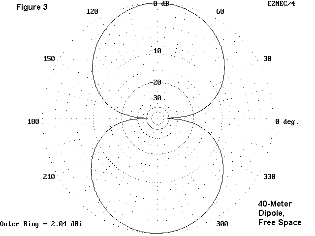
You will recognize the side nulls as corresponding to the side-pucker of the 3-D view. In free space, for a dipole, every slice through the donut would present the same view of the antenna pattern.
The elevation view of the pattern is a slice vertically through the 3-D pattern. It can be at any specified azimuth angle, but typically we choose the azimuth angle of strongest radiation. Here the angle is either 90° or 270°.
What determines the 90-270° orientation in part results from how the model was constructed. For a horizontal dipole, you can put the length of the antenna in the X dimension--which gives the pattern in Figure 3--or in the Y dimension--which would change the antenna orientation by 90 degrees. A Y-dimensioned dipole would show maximum radiation in azimuth directions 0° and 180°. (My preference for speed of making alterations is to put the longest or most changeable length in the X dimension. Hence, all broadside patterns will be oriented as in Figure 3.)
The vertical slice through the donut, of course, would yield a simple circle indicating equal power at all elevation angles. All NEC models presume the principle of reciprocity; that is, the pattern of power radiation equals the pattern of receiving sensitivity.
Antennas mounted over the ground are more complex, because the portion of the free space pattern representing downward radiation is reflected by the ground back upward in accord with basic optical principles, adjusted by the program for ground losses. The actual amount of ground loss for horizontal antennas does not differ greatly from great soil to very poor soil, so for most purposes, models are taken over average ground. The values of conductivity and the dielectric constant are usual built into the program as defaults.
Let's put a 40-meter dipole up 70' and look at its 3-D pattern:
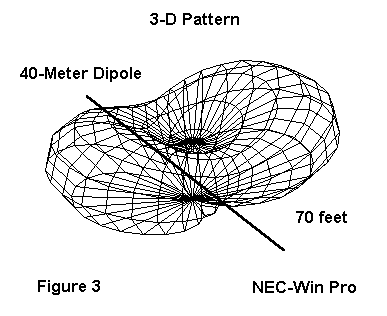
The exaggerated line represents the antenna wire. Here it passes at the base of the pattern through the bottom-most side puckers. Maximum radiation is broadside to the wire, but at upward angles.
The next step is to take an elevation pattern, a vertical slice through the direction of maximum radiation (from lower left to upper right). For this antenna, the angle will again be either 90° or 270° on the azimuth circle.
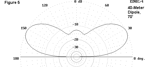
You can likely recognize the center "hump" from the 3-D plot and the upturned ends. Note that there is no radiation at 0° elevation angle because far-field plots are assumed to be so far distant that point-to- point and ground wave radiation are no longer factors that determine the pattern.
Creating an azimuth pattern involves choosing an elevation angle above 0°. We may use any number of bases for our selection, but two are most common. One is the angle of maximum radiation to see just what the maximum gain of the antenna may be and how the pattern at that angle looks. The model told me that the angle of maximum radiation (also called the "take-off" angle) is 27°.
Figure 6 displays the azimuth pattern of the dipole at its take-off angle. Remember that the pattern is actually a sort of cone, with the center of the pattern circle at the antenna height. The cone slopes upward all around the circle at an angle of 27° above the horizon. You can also see from Figure 6 that the maximum gain is 7.6 dBi.
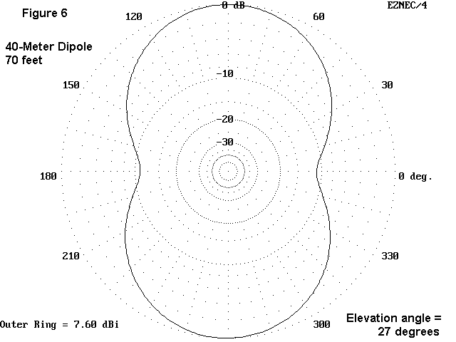
A second route to creating an azimuth pattern is to begin with an independent interest in some skip path angle. Suppose, for instance, that you have good reason to believe that the best path to Europe requires a skip angle of 17°. What would the antennažs pattern look like at that angle?
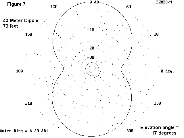
From Figure 7, it is clear that the shape of the pattern has not significantly changed relative to the pattern shape at the 27° elevation angle. However, the gain is down considerably. Looking at the 3-D pattern and the elevation pattern, we can see that this new cone slice is taken at an angle of lesser radiation.
The lobes and nulls of an antenna over real ground are functions of the phases of the direct or incident waves and the reflected waves as they occur at the same angles away from the antenna. Sometimes they are in phase and add, resulting in gain numbers far higher than the free space gain. We call this a lobe. In other parts of the overall pattern, they are out of phase with each other, partially or wholly canceling the radiation. We call this a pattern null.
One way to increase the amount of information in a pattern is to combine several elevation or several azimuth patterns into one graph. For example, if we had combined Figures 6 and 7, the lesser strength of the radiation at the lower angle would have been evident.
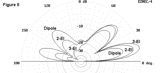
We can also combine elevation patterns. For example, place a dipole, a 2- element Yagi, and a 3-element Yagi at the same height and combine their elevation patterns in the azimuth of greatest radiation. You will see the evolution of the bidirectional dipole into a pattern with high forward gain and a high front-to-back ratio.
A second way to derive more antenna information from a modeling program is to frequency-sweep an antenna. Specify upper and lower frequency limits and the increments for spot checks between these limits. You can produce data on pattern changes, such as where the gain reaches maximum and where the front-to-back ratio (if relevant) reaches maximum. You can also watch the feedpoint impedance, both resistance and reactance, change across the sweep range. Some antenna designs are quite narrow, and one or more of their properties may change drastically even within a ham band. Others are broad and do not radically change any characteristics over wide frequency ranges.
Another instructive exercise is to watch the properties of an antenna change with height as you step the model height at regular intervals. Although most programs have frequency sweep capabilities, you will have to increase the model height manually. However, you may discover interesting changes of patterns or the feedpoint impedance along the way.
There are innumerable systematic questions you can pose to a modeling program, and the answers you glean can teach you much about antennas. Unfortunately, most antenna modeling program users make a few spot checks of their own antennas and then never open the program again. These folks lose fully 90% of the benefits of the program.
I have dwelled on the basics of antenna modeling because much in this
series will be derived from them or illustrated by them. In fact, you can
make a whole handbook of expectations from them.
Updated 4-29-97. © L. B. Cebik, W4RNL. Data may be used for personal purposes, but may not be reproduced for publication in print or any other medium without permission of the author.