 ANTENNAS FROM THE GROUND UP
So let's start again, looking at each of the elements in the antennažs name and seeing what we can discover about the dipole. Often maligned as too simple to be much good, the dipole turns out to be a rather fantastic antenna.

Everyone knows that a basic dipole looks like Figure 1. Now here is how the full name works:
1. Dipole: the antenna is a dipole because it has two "poles," that is, regions of the antenna where the current goes from maximum to minimum.
2. Center fed: The antenna is fed at its exact center.
3. Half-wavelength: the antenna is approximately 1/2 wavelength long.
4. Resonant: the feedpoint impedance, Z, which is ordinarily composed of resistive and reactive components (R ± jX), is purely resistive.
In addition, everyone knows how to calculate the length of our resonant half-wavelength center-fed dipole: L (in feet) is the length figured according to a simple recipe:

And everyone also knows that the feedpoint impedance of a resonant dipole is about 70 to 72 ohms. All we have to do to put up a dipole for 7.15 MHz is to apply the formula and cut our wire to a length of 65' 5.5" and hang it up.
First, the formula is only a ball park generalization, and not very accurate at that. Even in free space (a presumed volume in which the antenna is centered with absolutely nothing reflective in any direction), the formula does not match up well with NEC-2 models. Using #14 copper wire, the length of a free space dipole for 7.15 MHz is 66.95' and its feedpoint impedance is 73.6 ohms.
Second, the formula is shorthand for a more accurate equation:

where K is a shortening factor due to what some treat as capacitance off the ends of the wire elements. The standard formula assumes a value for K of 0.95.
Values of K appear in handbooks as graphs, the origin of which no one currently remembers. These graphs and the presumed figure of 0.95 are once more ball park numbers. For a more correct readout of values of K, see "Calibrating K to NEC," QEX, March, 1996, pp. 3-8, or HAMCALC.
K varies with the wire size: the larger the diameter, the lower the value of K. It also varies in a minor way according to antenna material, with higher loss material showing a lower value of K. No single value can capture every wire size used by antenna builders. We can construct with spreads of wires effective diameters up to a foot or more. By comparison, #12 AWG wire is 0.0808" in diameter.
While we are focused on wire diameter, we might also note that fatter wires also increase the bandwidth of a dipole. We tend to define bandwidth in terms of SWR. An antennažs bandwidth might be said to be the frequency spread between those frequencies at which the antenna shows a 2:1 SWR relative to its natural resonant impedance. Changing wire size from #34 at the thinnest end of the line to about 2" at the upper end results in an increase in bandwidth of over 2 to 1. For other comparisons, see the Bandwidth program in HAMCALC.

You may think that the gain in dBi of this NEC-2 model is too low, for we have all ben told that a dipole's gain in free space is about 2.15 dBi. However, #14 copper wire has some (small) loss, which the model incorporates.
Unfortunately, from 160 meters to 30 meters, our antennas are usually less than 1/2 wavelength in height. Therefore, the real dipoles with which we operate show considerably different traits from our free space model. The Sommerfeld-Norton ground calculation system permits accurate models of low antennas, with the limitation that the antenna is modeled over level ground free of the ground clutter of real ham installations.
At heights below 1/2 wavelength, the resonant length of an antenna will vary considerably from the free space length. (By way of contrast, the fluctuations of all properties of antennas above 1/2 wl grow much smaller, reaching relatively insignificant proportions for most, but not all, types of antennas above 2 wavelengths. See "The Effects of Height on Other Antenna Properties," Communications Quarterly, Fall, 1992, pp. 57-79.)

Figure 3 graphs the changes in the resonant length of the dipole in 1/8 wl increments from 1 wl down for a 7.15 MHz dipole. The same pattern, with only insignificant variations due to such factors as the wire diameter-to-length ration, ground penetration of RF energy, etc, will hold true for all dipole in the 160-meter to 30-meter range, so long as height is measured in percentages of a wavelength.
The traditional way of presenting this information has been to show the variation in feedpoint resistance and reactance with height, but this graph gives the builder a better idea of just how long the dipole must be.

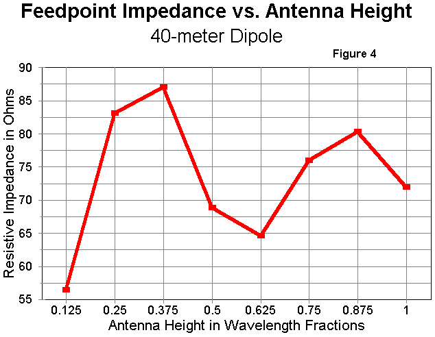
From the second graph, we can see that the resonant feedpoint impedance (a pure resistance) also varies considerably as the height changes. Contrary to some accounts, the impedance goes above 70 ohms as well as below it as the antenna height changes. The curves are actually smooth, but many more data points would have been needed to establish that fact.
In order to translate the graphs into feet above ground, here are some figures for the low ham bands:
160 meters: 1.9 MHz: 1 wl = 517.7' or 157.8 meters.
80 meters: 3.5 MHz: 1 wl = 140.4' or 85.7 meters.
75 meters: 4.0 MHz: 1 wl = 245.89' or 74.95 meters.
40 meters: 7.0 MHz: 1 wl = 140.5' or 42.8 meters.
30 meters: 10.1 MHz: 1 wl = 97.4' or 29.7 meters.
Figures for the gain of a dipole are even trickier to handle. At very low heights, such as 1/8 wl, almost all of the radiation of a dipole is straight upward. Even at twice the height, the angle of maximum radiation is about 60° and drops to the 28-30° range at 1/2 wl in height. Consequently, it makes little sense to compare gain at maximum angles of radiation for dipoles below 1/2 wl in height.
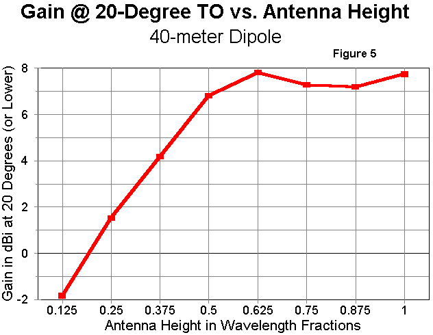
However, it is possible and practical to choose an semi-arbitrary low angle of radiation and make comparisons. I have chosen 20° elevation as the comparison point, using either it or the maximum radiation angle, if the latter is lower than 20° elevation. This comparison gives a measure of long-distance performance capability of the antenna as its height changes up to 1 wl.

The chart has several interesting features. First, it shows a negative gain figure for the lowest height. This figure does not mean that the antenna will not work, but merely that its gain is less than an isotropic radiator. (Mathematical systems, such as NEC, use a theoretic isotropic radiator for calculations, but Brian Beezley, K6STI, has shown that a good approximation of one can be built.)
Second, the gain at 20° elevation increases rapidly as the antenna is raised, reaching a peak at about 5/8 wl. The angle of maximum radiation for this height is 22° while the angles for the remaining heights are 19°, 16°, and 14° respectively. Note especially the dip in gain in the 7/8 wl region.
The explanation for this dip lies in the way in which secondary lobes develop as the antenna is raised. The phase relationships of the direct "ray" and the ray reflected off the ground (with some loss) changes as the antenna goes up, resulting in complex collections of lobes and nulls vertically around the antenna.

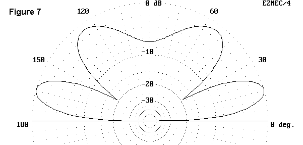
At 1/2 wl, almost the entire radiated energy is concentrated in two broad lobes, one opposite in direction from the other. The elevation pattern of Figure 6, for a 40- meter dipole at a height of 1/2 wl, clearly shows the concentration of energy.

In contrast, Figure 7, shows the same antenna at 7/8 wl. A second lobe, virtually straight up and with considerable energy content has made its appearance. Except for some very special purpose, the nearly vertical lobe represents a waste of communications energy. Hence, antenna heights in the 3/4 wl to 7/8 wl should be avoided, even with upper HF frequency antennas. One other factors bears noting in our saga of the dipole: the front-to-side ratio. One reason for using a dipole (other than just to make contacts, although that is a good one) is to take advantage of the antenna's bidirectionality. By broadsiding it to the stations or areas we want to work, we also gain nulls in directions from which we do not want to hear.
However, the front-to-side ratio of a dipole increases dramatically as the antenna height is raised. The following graph tells the story. Once more, I have used the 20° angle until the antenna was high enough to have a main lobe below that angle.

The information on the graph can be illuminated by a pair of azimuth patterns for dipoles: one at 1/8 wl and the other at 5.8 wl. In the first case, Figure 9, the pattern is a broad oval, with almost no rejection off the sides. In the second, Figure 10, the pattern shows that it is growing toward the figure-8 of free-space fame. It would take several wavelengths of height (achievable only at VHF and up) for the nulls to reach 30 dB deep.


This exercise has not been aimed at giving you advice on where and how to
install your dipole. Instead, it has tried to make you better informed
about how and how well low-altitude dipoles work. Remember that even at 50
feet up, a dipole has more gain at 20° than any of the Delta Loops,
although those antennas quiet the high angle incoming QRM, QRN, and noise.
Nonetheless, a dipole is a good antenna, and gets better the higher we
install it. For its simplicity, it is nothing short of incredible.
Updated 4-27-97. © L. B. Cebik, W4RNL. Data may be used for personal purposes, but may not be reproduced for publication in print or any other medium without permission of the author.