 ANTENNAS FROM THE GROUND UP
When we began our study of vertically oriented 1 wl loops, we restricted ourselves to feeding the loop so that it acted like a variant of a dipole, with predominantly horizontal radiation. In that radiation, there is a vertical component that many low-band DXers find extremely useful. However, we shall have to give up something to get the DX advantage: gain. But, as we shall see, gain is not everything in this world.
Interestingly, we shall make only one significant change in the loop antennas we have studied: the position of the feedpoint. We shall also alter the size of the antenna slightly to bring it to resonance (for reasons to be told as we go along). We then have a vertically oriented, vertically polarized loop (VOVPL). It will look the same as a VOHPL to any outsider, but it will be electrically different. Instead of a spread (folded) dipole, we shall have a pair of phased quarter-wavelength verticals. In fact, these loops become close kin to the half-square, a fact that one can prove to oneself with either modeling software or an actual antenna.
As verticals, the loops and the half square share a fascinating advantage: they require no ground plane, counterpoise, or other massive and messy wire structure other than the antenna/phase-line itself. In another episode, we shall look more closely at what ground planes really amount to at HF. For now, it suffices that the loops and half-square free us from the dirt-digging, wire stringing part of vertical antennas.
We buy this advantage by accepting a disadvantage: many of these antennas must be fed part or all the way up a vertical or sloping leg. And the antenna is essentially a one-band affair, since its performance on bands above the fundamental is too poor to be worth mentioning (unless one moves the feedpoint and converts the antenna back into a VOHPL).
Anyone wishing seriously to understand large loops for the lower HF bands should study Chapter 10 of Low-Band Dxing by John Devoldere, ON4UN. He was among the first to understand the VOVPL as two quarter wavelength (nearly) vertical antennas connected by a half-wavelength nonradiating phasing line.
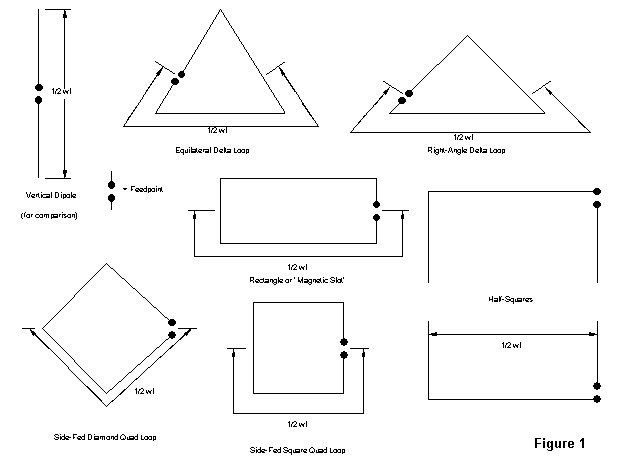
Figure 1 shows a collection of antennas having something in common. In each case (except for the 1/2 wl vertical dipole, shown for size reference), part of the antenna can be viewed as a nonradiating phase line, and part as a pair of vertical radiators connected together at the their tops. However, if 1/2 wl provides the optimum spacing between radiators, then all but the half-squares are less than optimum. As we shall see, the other designs will have less gain than the half-squares, just as one might suspect from spacing them too closely. The half-squares have another unique feature: the verticals are not top-connected.
Top-connection is actually unnecessary. (It is, however, very convenient mechanically, since it permits a single length of wire to form a loop.) Using NEC models or VHF antennas, you can verify this fact with a little experiment: build a loop (for example, the right-angle delta) that is resonant on a desired frequency. Then snip the top connection and separate the wires by a tiny amount. Antenna properties will not change. This includes the currents and their phases along the wire lengths. As you widen the gap, changes will occur in light of the changing geometry created by further separation. Eventually, you will arrive at the half square configuration.
The quad configurations are not usually thought of in these terms, due to the complexities of their lower structures marked by the 1/2-wl indicators in Figure 1. However, these complexities are not different in principle than those created by the bends in the delta phase line. The chief result of bending the phase line is incomplete cancellation of radiation from the line and less than optimum spacing of the verticals for maximum gain.
Let's look more closely at a few samples of 40-meter (7.15 MHz) VOVPLs.
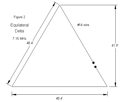
Compared to VOHPLs, VOVPLs will be slightly larger for resonance, and resonance will be important for some VOVPL designs, since they will be fit for direct coax feed. Here are some numbers for the equilateral delta, fed 25% up one side (or, 1/4 wl from the apex). Note the low elevation angles of maximum radiation, but at the cost of most of the horizontally polarized radiation at higher angles for the equilateral delta of Figure 2.
Height           Gain     TO       Impedance
Min      Max     dBi      Ang      R +/- jX
10'      51.9'   1.1      21°      160 - j8
20       61.9    1.4      18       130 - j24
30       71.9    1.5      16       115 - j20
It is also possible to feed the equilateral delta at a lower corner, with a somewhat different pattern, as shown in Figure 3.
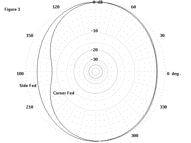
When fed in the corner, the figures for the equilateral delta look like this:
Height           Gain     TO       Impedance
Min      Max     dBi      Ang      R +/- jX
10'      51.9'   1.0      29°      150 + j2
20       61.9    1.6      25       135 - j15
30       71.9    1.8      22       125 - j20
The equilateral delta is slightly directional away from the feedpoint, with a bit of rejection to the feedpoint side. It is the only loop among those reviewed here that shows this pattern; in all other cases, displacement is negligible.
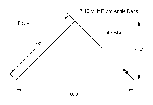
Although it has a longer baseline, the right-angle delta in Figure 4 is more compact vertically. It is fed about 12-15% up one sloping leg, or about 1/4 wl from the apex of the triangle and has a half dB more gain than the equilateral delta.
Height           Gain     TO       Impedance
Min      Max     dBi      Ang      R +/- jX
10'      40.4'   1.6      23°       80 + j15
20       50,4    1.9      20        61 + j0
30       60.4    2.0      17        52 + j0
With most VOVPLs, figures for the angle of maximum radiation and for gain begin to increase only slowly once the baseline is 20' up. Figure 5 compares the elevation patterns for the right-angle delta with 10' and 30' baseline heights. The patterns are typical of almost all the VOVPLs.
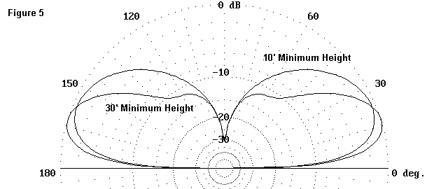
The right-angle delta can also be fed at its corner, with only slight decreases in gain and no practical change in take-off angle. This feature is a convenience to antenna builders, since the coaxial cable--extremely relevant to this antenna as a direct-feed system--can be handled more simply. It can be dropped to the ground, and buried, if necessary.
Height           Gain     TO       Impedance
Min      Max     dBi      Ang      R +/- jX
10'      40.4'   1.3      24°       90 + j12
20       50,4    1.7      20        70 - j3
30       60.4    1.8      17        60 - j3
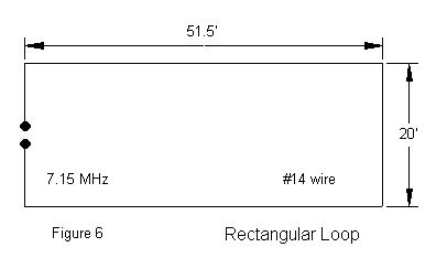
The rectangle (Figure 6) is more practical than the square quad loop, so let's focus on this shape. There is nothing magical about the 20' vertical height, and other heights can be used. Like the other VOVPLs, the rectangle is larger at resonance than when fed bottom center. It also has more gain than either of the delta loops, largely due, I suspect, to the fact that the high-current portions of the vertical radiators are parallel.
Height           Gain     TO       Impedance
Min      Max     dBi      Ang      R +/- jX
10'      30'     2.2      24°       61 + j12
20       50      2.6      20        45 - j2
30       60      2.8      18        40 - j3
With only a slight drop in gain, the rectangle may be fed at a lower corner for ease of feedline handling.
Height           Gain     TO       Impedance
Min      Max     dBi      Ang      R +/- jX
10'      30'     2.0      25°       75 + j10
20       50      2.4      21        60 - j8
30       60      2.6      18        50 - j11
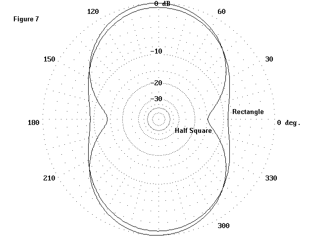
One of the differences in the pattern of the rectangle and the half-square (whose details follow almost instantly) is side rejection. Although the gains are similar, the half-square has more side rejection, while the rectangle shows the more classic oval, as shown in Figure 7. Whether side rejection is an advantage or a disadvantage may have something to do with your choice between these antennas.
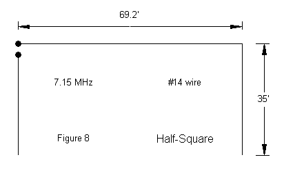
The half-square, shown in Figure 8 and brought back to current ham attention by N4PC some years back (although it is much older), is the most optimally spaced phased vertical array among wire antennas. Conventional ham construction inverts the configuration, relative to the deltas. In free space or at a height of several wavelengths above ground, the antenna can be used pointing up or pointing down with no dimensional changes. In fact, I built a version of this antenna, pointing up, for 146 MHz, where it provides the highest gain and deepest side nulls of any vertically polarized antenna I have examined.
At 40 meters, the antennažs proximity to the ground compels the inverted arrangement. Since the vertical tips are high voltage-low current points, changes in height will dictate changes in element length. The dimensions shown in Figure 7 are optimized for a minimum height of 5 to 10' above the ground.
Height           Gain     TO       Impedance
Min      Max     dBi      Ang      R +/- jX
 5'      40'     3.1      21°       60 -  j0
10       45      3.15     20        55 - j8
15       50      3.0      18        50 - j12
20       55      2.9      17        50 - j14
As the height is further increased, the elevation of the high current points on the vertical radiators will also begin to result in a higher angle radiation lobe, which takes power from the lowest lobe. Therefore, it is best for lower HF use to keep the half-square fairly close to the ground.
Which version of the VOVPL you choose to build will depend as much upon the physical features of your available space as upon the characteristics of the various versions we have examined. If you have only one high support, one of the deltas may be your only choice. If you have more lateral than vertical space, the rectangle or the half-square may fit your needs. Just keep the antennažs broadside toward the DX you want to work.
Using a VOVPL also requires that you change your way of thinking about reception. The absence of high-angle sensitivity automatically reduces the total volume of noise you will pick up. This increase in quieting is additional to the normal reduction of noise of a loop over an antenna with free ends.
However, the VOVPL will not increase the signal strength of incoming DX signals. Some versions, like the half-square, may show very slight increases in very low angle signal strength relative to a dipole at the same maximum height, but the differences will be small.
The advantage of the VOVPL lies in signal-to-noise ratio. Since receivers have excess gain that we seldom use, audio levels are easily increased to whatever you prefer. With a VOVPL, the faint DX signal will stand out against the noise. It takes some getting used to and practice to use a VOVPL effectively. If you use shorter skip signals to test the effectiveness of the antenna, you will likely be disappointed.
Since noise is not a consideration with transmitted signals, do not expect your signal to increase dramatically at the other end of the DX path. However, unless you can place a dipole very high, your transmitted signal will not suffer any decrease in the ears of the DX.
If you like to work a combination of short and long skip stations, you should consider having two antennas--perhaps a multiband dipole and a VOVPL. Of course, when you win the sweepstakes, you can replace both with a single, 200' high 80-40-30 meter beam.
Updated 04-04-2000. © L. B. Cebik, W4RNL. Data may be used for personal purposes, but may not be reproduced for publication in print or any other medium without permission of the author.