 ANTENNAS FROM THE GROUND UP
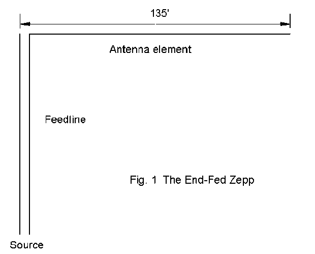
The Zepp can be cut for other bands, but a 135' length of #14 wire at a height of about 35' is one of the most common ham installations. 35' is only about 1/8 wavelength at 80 meters and about 1 wavelength at 10 meters. Therefore, the Zepp will exhibit all the variability and sensitivity to terrain of any low horizontal antenna.
The distinguishing feature of the Zepp is that it is fed at a high-voltage low-current point. Hence, its impedance is very high. More significantly, the impedance will usually have a large reactive component: capacitive if a tad longer than a multiple of a half wavelength, inductive if a tad short of a half wavelength. At the center point of an odd multiple of a half wavelength, the impedance of an antenna will be low with slow changes in reactance. At even multiples of a half wavelength, the impedance will be high. The reactance climbs to a very high value of inductive reactance and with only a tiny lengthening of the antenna (or increase in frequency) swings suddenly to a very high value of capacitive reactance that will gradually drop as the antenna is further lengthened (or the frequency climbs higher). 135' will prove a smidgeon long at all test frequencies.
Because the antenna is fed at a high-voltage point, the current along the feedline is not nearly so unbalanced as some have believed, especially on the fundamental frequency. End-fed Zepps rarely create problems of RF in the shack. One side of the line goes to the very high antenna impedance, the other side to the almost indefinitely large impedance of the missing antenna connection. Hence, the lines are fairly well in balance. However, balance is not perfect, especially as the frequency is increased. If balance were perfect, the line would show very low values of impedance for most of each half wavelength, making a match to the ATU very difficult.
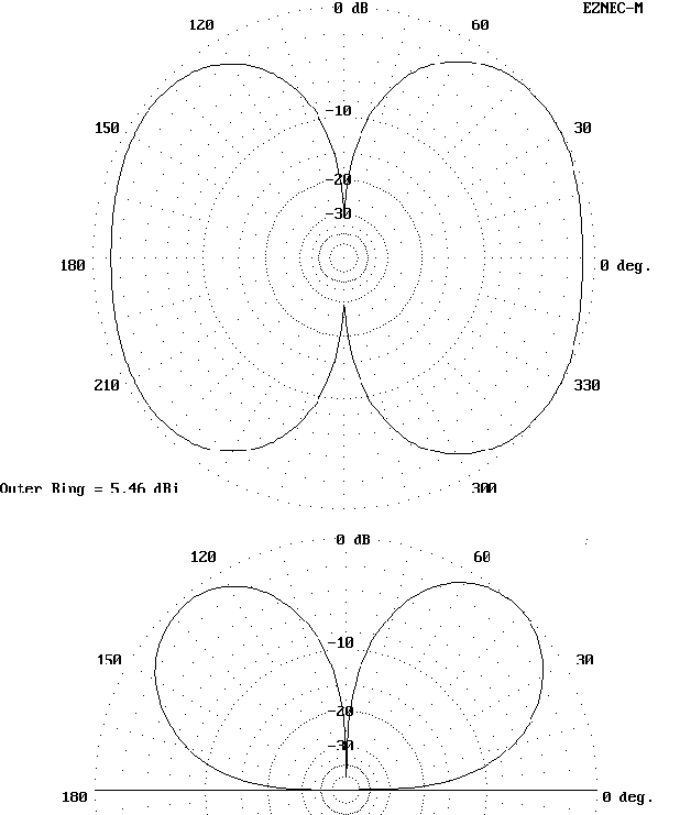
Imbalance between the wires of the feedline does create some radiation from the feedlines. However, its consequences on the overall radiation pattern depend on the length of the feeder, the frequency of operation, and the angle at which the feeder leaves the antenna. We shall show patterns for the Zepp assuming a. that all radiation is in the antenna and b. also with a 34' 410-ohm feeder. The pattern you achieve with your Zepp will depend on your layout.
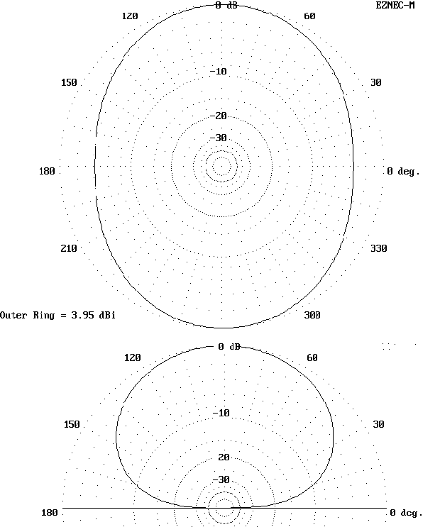
Note: Since the actual elevation angle of maximum radiation is greater than 45 degrees, the azimuth patterns are taken at an elevation angle of 45 degrees.
With feedline: Z = 15 - j420 ohms -- Elevation angle = 45 degrees
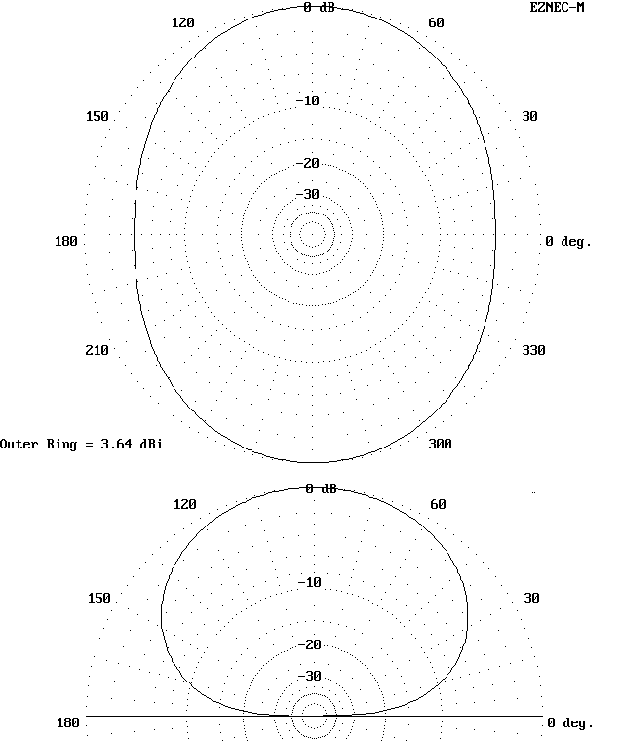
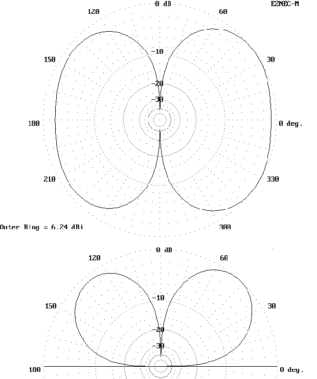
All impedance figures are very rough approximations to indicate the range of values. They are in no case the actual figures individual layouts will achieve.
With feedline: Z = 17 + j5 ohms -- Elevation angle = 45 degrees
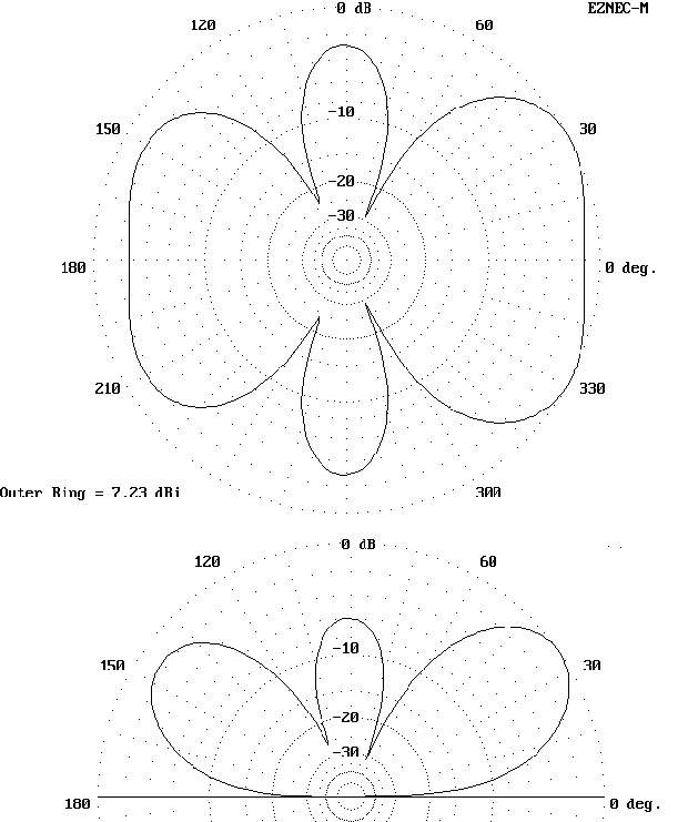
Note that at this frequency, the feedline radiation actually lowers the elevation angle of maximum radiation, a fairly rare occurrence with shorter lengths of feedline.
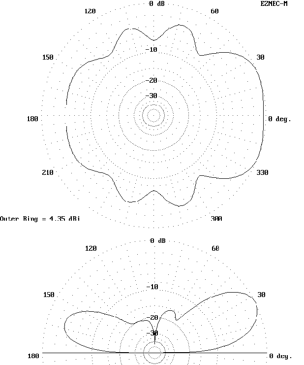
With feedline: Z = 30 + j280 ohms -- Elevation angle = 32 degrees


The feedline radiation below significantly rounds all the lobes of the azimuth pattern and reduces maximum gain while increasing overall broadside radiation.
With feedline: Z = 7500 + j2000 ohms -- Elevation angle = 26 degrees

On 17, the two patterns return to close coincidence. Whether patterns are similar or different will vary with feedline length and dress, as well as frequency.
With feedline: Z = 55 - j400 ohms -- Elevation angle = 20 degrees


Note that even though the pattern differences appear very minor, they are enough to reduce maximum gain below by a full dB.
With feedline: Z = 50 - j90 ohms -- Elevation angle = 17 degrees
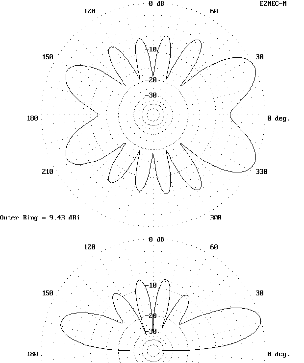
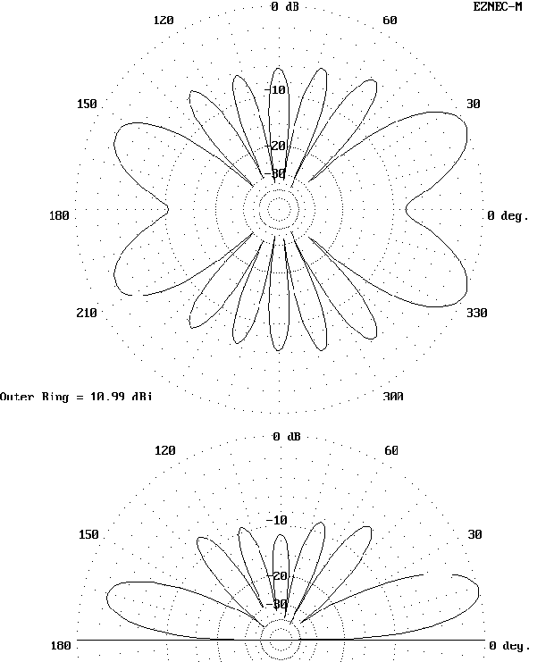
Note how slight thickening of the elevation lobes produces a significant decrease in the maximum gain of the main lobes of the pattern.
With feedline: Z = 45 + j370 ohms -- Elevation angle = 14 degrees

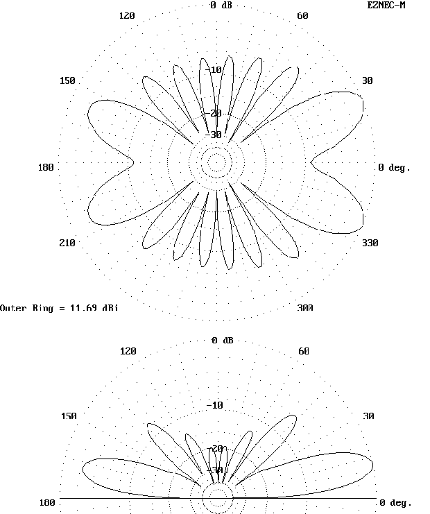
Although your situation is unlikely to copy this one, studying the upper and lower patterns for each band may give you a better idea of how to compare the details of antenna patterns.
With feedline: Z = 4750 + j720 ohms -- Elevation angle = 13 degrees

Updated 1-21-98. © L. B. Cebik, W4RNL. Data may be used for personal purposes, but may not be reproduced for publication in print or any other medium without permission of the author.