 ANTENNAS FROM THE GROUND UP
To review, our OCF looks like this:

I am taking this long on the OCF for a couple of reasons. First, the antenna has been the subject of considerable speculation, not to mention overzealous claims. These have obscured or ignored many of the basic facts about OCF operation. Second, antenna modeling is growing more popular. For newcomers to this higly educational activity, there is a temptation to accept what the machine says without checking the basic adequacy of the model fed to the machine. Hence, some added notes about modeling the OCF might prove useful to new owners of NEC and MININEC.
How the Harmonic Stuff Got Started: When the OCF first appeared on the ham scene, vacuum tube output stages were in vogue. Initially, these stages used parallel-tuned high-impedance output circuits with tuned link coupling to transform the tube's 1200 to 3000 ohm impedance to something closer to feedline impedances. Later, PI networks came into popularity for their ability to permit bandswitching, but wide ranging adjustment of the circuit remained possible.
Either type of adjustable circuit would match the tube impedance to a wide range of output impedance requirements. A range of 20 to 200 ohms was not uncommon. Without an ATU, one might directly match lines presenting up to 4:1 SWR levels with good efficiency of power transfer. The OCF was popular as a directly matched antenna on its fundamental and most of its even harmonics.
Even before the advent of fixed tuned solid state output stages, manufacturers began removing the "load" control from the new SSB transceivers. Thus was born the 2:1 SWR limit of ham transmitter output stages. Suddenly, OCF users began to have troubles effecting a direct match from the feedline to the transmitter. Since the dang system put RF into the shack anyway, many simply chose other types of antennas. From the 1960s to the 1980s, the OCF went into decline. Then came some US and Canadian hams with new antenna kits and new claims for the antenna. These resulted largely from the ease of making matching transformers using the more readily available iron and ferrite cores. We thought we could hit that magic 300-ohm or equally magic 100-ohm point and match our way to a mutliband antenna.
Some purveyors of OCF kits said "Put them up at 35' in a field free and clear of ground clutter." When buyers complained that the antenna seemed not to work on one or another band, the sellers simply blamed the operator's site (and gave no refund). Some have suspected that other kit makers have intentionally or unwittingly used a fairly lossy matching device at the antenna-feedline junction to make a match on all advertised bands "at any cost."
So we have two questions to answer: a. What happens to the impedance of an OCF on the even harmonics? And b. Are the patterns on these harmonics as good as they are claimed to be? Once more, we shall use our friendly old center-fed half-wavelength dipole as the standard of comparison.
Impedance: First, the resonant lengths of an OCF are not directly harmonically related. The following four tables show the resonant frequencies of the fundamental and even harmonics for a 7.15 MHz OCF at 70' and at 35' for fundamental impedances in the 100-ohm and the 300-ohm vicinities. Resonance is defined for this exercise as a feedpoint impedance with less than 1 ohm reactance. Dimensions are listed as minus and plus either side of the feedpoint.
1.  Length:  -10.4'/+57.35'
Height: 70'    Material: #14 copper
Frequency      Impedance
 7.15 MHz      302 ohms
14.34 MHz      138 ohms
28.77 MHz      130 ohms

2.  Length:  -11.71'/+55.15'
Height: 35'    Material: #14 copper
Frequency      Impedance
 7.15 MHz      298 ohms
14.56 MHz      117 ohms
29.13 MHz      173 ohms

3.  Length:  -20.21'/+47.15'
Height: 70'    Material: #14 copper
Frequency      Impedance
 7.15 MHz      102 ohms
14.38 MHz      107 ohms
29.0 MHz       312 ohms

4.  Length:  -24.89'/+41.48'
Height: 35'    Material: #14 copper
Frequency      Impedance
 7.15 MHz        98 phms
14.63 MHz      191 ohms
29.37 MHz      115 ohms
The resonant frequencies of the harmonics of the fundamental frequency to which the antenna is originally cut depart more radically from true harmonics the closer the antenna is to the ground in terms of fractions of a wavelength. Note that since the model used in this exercise is for 40 meters, an 80-meter OCF at 35' and 70' would be only 1/8 and 1/4 of a wavelength in height, respectively.
At true harmonics within the ham bands, the feedpoint impedance of the antenna on 20 and 10 meters would contain a large reactive component. Although this situation is not significant for a system consisting of parallel feedline and an antenna tuning unit, it presents major problems for systems using a balun and coaxial cable. Transmission-line transformer baluns of the type designed and investigated by W2FMI require resistive loads.
The impedances at the feedpoint for ham bands which are not even harmonics of the antenna's fundamental frequency are not suited for balun operation. If the antenna is to be used on any of these amateur bands, parallel feedline and an ATU is a must.
Patterns: The azimuth patterns for a center-fed half-wavelength dipole operated on harmonic frequencies are quite different from those of the harmonics of an OCF. Interestingly, with or without feedline radiation, the elevation angles of maximum radiation are the same for either antenna, making pattern comparison relatively uncomplicated. For comparison, here are the azimuth patterns for the center-fed antenna:
1. 7.15 MHz; elevation angle 27 degrees
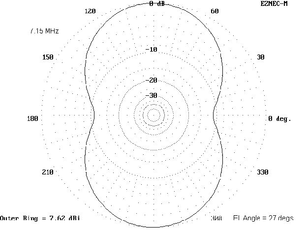
This pattern is not significantly different from that of an OCF when the antenna element alone is presumed to radiate. The side rejection of is about 11 dB.
2. 14.15 MHz; elevation angle 14 degrees

The second harmonic of a center-fed half-wavelength dipole yields a full wavelength antenna with a high feedpoint impedance, along with higher maximum gain in a narrower beamwidth.
3. 28.5 MHz; elevation angle 7 degrees

To get a feel for how the OCF differs in harmonic performance, let's look at azimuth patterns for the same frequencies and elevation angles for OCFs in which only the antenna element is presumed to radiate. These antennas are modeled for a 300-ohm feedpoint impedance.
1. 7.15 MHz; elevation angle 27 degrees

This pattern is indistinguishable from the pattern of the center-fed dipole shown above. Wherever patterns are identical, antenna performance will also be identical. Harmonic patterns, however, will differ considerably.
2. 14.15 MHz; elevation angle 14 degrees
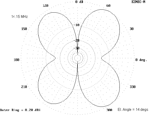
This cloverleaf most resembles the 10-meter pattern of the center-fed dipole. The pattern may be more useful for general communications than the bi-directional pattern of the center-fed dipole, although the dipole pattern can reduce QRM from the sides more effectively.
3. 28.5 MHz; elevation angle 7 degrees
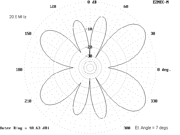
The 8-lobe pattern of the OCF operated on 10 meters is distinctly canted toward the longer end of the antenna. However, do not confuse the relatively high gain with that of a beam. Even a simple 2-element Yagi at a half-wavelength height will have slightly more gain and at least 2 S- units of front-to-back ratio.
Claims have been made to the effect that allowing the feedline to radiate provides benefits in the signal pattern. To test this claim, let's look at azimuth patterns for 7.15 MHz, 14.15 MHz, and 28.5 MHz for an OCF at 70' height and designed for the 300-ohm feedpoint. The radiating feedline is presumed to be restricted to 10' by use of a line isolator or W2DU choke.
1. 7.15 MHz; elevation angle 27 degrees

2. 14.15 MHz; elevation angle 14 degrees
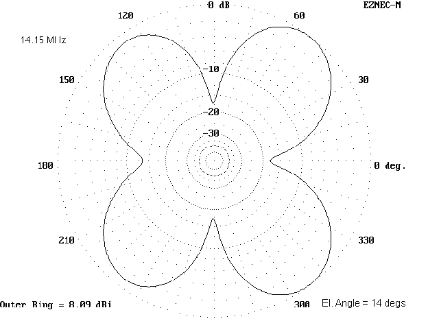
3. 28.5 MHz; elevation angle 7 degrees

In all cases, the antenna gain is down slightly. Only in 10-meter operation does the antenna show any marked effects from the vertical radiator, as four of its lobes disappear into one broad and modest lobe. For operational purposes, the likely effect of using the short section of feedline to supplement radiation from the antenna element is negligible.
To be fair, let's also look at the case of using 35' of the feedline as a supplemental radiator. Compare each of the azimuth patterns (all of which have the same elevation angle of maximum radiation as the preceding patterns on each band) with its corresponding patterns above.
1. 7.15 MHz; elevation angle 27 degrees

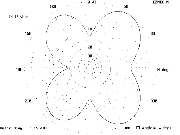
2. 14.15 MHz; elevation angle 14 degrees
3. 28.5 MHz; elevation angle 7 degrees
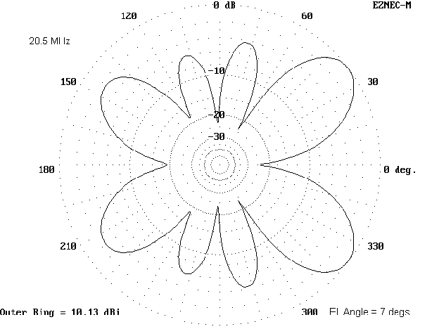
A comparison of the patterns using 10' of feedline radiator and 35' of feedline radiator demonstrates the variability of the effect of supplementing the antenna element's radiation. The 10-meter pattern has returned to its shape with no feedline radiation, while the 20-meter pattern shows more cant toward the long end of the antenna and the 40-meter pattern shows a measurable decrease in gain with only a slight widening of the pattern off the antenna element ends.
In the final analysis, it is doubtful that feedline radiation will either significantly help or significantly harm the performance of an OCF antenna. Feedline radiation will affect the presumed impedance of the antenna, making it less predictable. Consequently, the use of an ATU is always a wise procedure.
However, if one is going to use an ATU, then maximizing the use of parallel feedline is the surest way to reduce losses. As noted in the initial installment on this antenna, conversion to coaxial cable at the shack entrance may be necessary to prevent RF on equipment cases. This precaution is wise even at QRP, since RF in the shack is lost to propagation.
We have one more question to ask: how does the OCF perform as an "all-band" antenna? But we shall save that question for next time.
Updated 1-25-98. Š L. B. Cebik, W4RNL. Data may be used for personal purposes, but may not be reproduced for publication in print or any other medium without permission of the author.