 ANTENNAS FROM THE GROUND UP
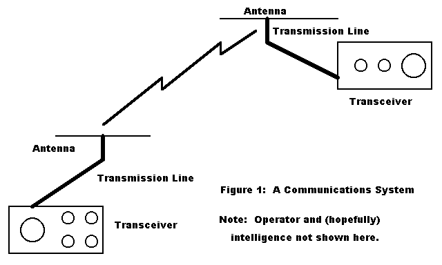
Antennas? Unfortunately, feedlines and antennas are too often looked at as accessories, as if the "rig" was the most important thing in the world in a communications system. And that has blocked our attention to and understanding of antennas. So let's start all over again by looking at a communications system. See Figure 1 for a sketch of a basic system.

As you can see, a true communications systems consists of at least two stations: either a minimum of two or no communications will occur. Each station receives and transmits. Each needs devices to receive and to transmit. What transmitting and receiving have in common--usually, but not absolutely always--is a transmission line and antenna. For some special purposes, like working 160 meters, some folks use separate receiving and transmitting antennas, and separate feedlines.
Although this may seem very basic, let's review the functions of these components of the communications system:
Transmitter: a collection of circuits (composed of components) that generates RF electrical energy and modifies it to include intelligence.
Receiver: a collection of circuits (composed of components) that separates the intelligence from the incoming RF electrical energy for station use.
Transmission line: transfers RF electrical energy from the transmitter to the antenna with minimal loss. Also transfers RF electrical energy from the antenna to the receive with minimal loss. Required only when the antenna is remote from the transmitter.
Antenna: a transducer that converts RF electrical energy into electro- magnetic radiation or fields and which converts intercepted electro- magnetic radiation into RF electrical energy.
Interestingly, if we connect the transmitter and receiver directly to the antenna, as we virtually do with VHF handhelds (walkie-talkies?), we can eliminate the most interesting part of the communications system: the transmission line. Transmission lines are not interesting just because they seem mysterious. They are especially interesting because they are the key to everything else. Some traditional treatments of communications electronics begin with transmission line theory. From there, they derive lumped components (capacitors and inductors) and then they also derive antennas.
Notice that I said "lumped components (capacitors and inductors)." I did not say "capacitance and inductance. One of the things we have to do to understand antennas and transmission lines is to separate in our minds the ideas of things--the capacitors and inductors--from the basic phenomena-- capacitance and inductance. Capacitors and inductors are just the things we use to implement controlled amounts of capacitance and inductance when and where we want them.
Transmission lines also exhibit capacitance and inductance. Every length of wire exhibits inductance, and every pair of surfaces (like wire surfaces) exhibit capacitance. Although transmission lines come in many varieties ranging from one wire to many, the two wire line--coax or parallel--is most familiar to us. Two wires with a finite length equals capacitance and inductance.
Transmission lines have something else of note: standing waves. A standing wave is nothing more than the variations in voltage and current along a transmission line. When measured and plotted on a graph, they replicate an electrical wave as we are accustomed to picturing it: something more or less like a sine wave with many possible variations.
Standing waves are functions of basic electrical properties: If we pass a current through a wire, it generates an electro-magnetic field. If the electrical energy is alternating current (AC) and high enough in frequency (RF), then that field will radiate, that is, be detectable at a distance. It will be detectable unless we can control and confine it. Transmission lines confine the field by having equal but opposite voltages and currents on each wire in a two wire system in close enough proximity so that the fields cancel each other.
For a full account of the parameters of coaxial transmission lines, see QEX, August, 1996, pp. 3-10.
Now let's look at our lumped components: If they were large enough, they would have standing waves. They still have fields. If they did not, the grid-dip oscillator would not work. Of course, we try to control and confine component and interconnection-wire fields by a lot of methods. We confine inductor fields with iron or ferrite coil cores. We position components relative to each other for minimum coupling. We install shielding to keep inside fields from interacting with outside fields. Remember, however, that we can make use of component radiation. For example, we can make a large planar coil for the plate circuit of a tube and use it simultaneously as a lumped component in the circuit and as a loop antenna not especially less efficient than those used externally to the transmitter. (See, for example, Communications Quarterly, Winter, 1994, pp. 7-8.)
Since every capacitor exhibits some inductance and every inductor exhibits some capacitance (again, controlled to a minimum for predictable circuit use), every lumped component is a sibling of a transmission line. Just ask VHF designers who use transmission line components instead of inductors.
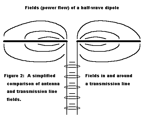
What about the other end of the transmission line: the antenna? Are they transmission lines? According to a traditional analysis, still very useful for low and very low frequencies, we can visually and mathematically picture an antenna as a transmission line spread apart so that the wires are collinear (end to end) rather than parallel. See Figure 2 for a very simplified sketch of the antenna and one of its several types of fields. A lot of stuff happens if you do open up the transmission line in this way.

First, the fields around the wires are no longer confined by equal but opposite adjacent fields. Second, the intensity of the field and its phase may be just far enough away so that they add to the total field intensity in some directions and subtract from it in others.
In a transmission line, only enough power is consumed to overcome the losses of the wire system relative to establishing the fields of the standing wave. The remainder of the power supplied by the source is available at the other end of the line for the load. Of course, if we manage to unbalance the transmission line, it will act like an opened transmission line for that part of the voltage and current not in balance. In other words, it will act like an antenna.
The antenna is the transmission line's load in a transmitting situation because its fields are no longer confined. The current along the line yields fields that may spread without limit (with respect to the system). In short, the electrical energy is transformed into electro-magnetic radiation, and it must be resupplied from the source to maintain the ever-expanding fields.
If you are ready for a little surprise, the energy of an antenna does not in fact travel in the antenna wire or tubing. It travels along the field lines in Figure 2 outside the wire or tube. In addition, the energy in a transmission line exhibits the same property. We shall look deeper into this mystery in another installment.
On the receiving side, the antenna is always intercepting electro-magnetic fields, which set up currents in (or along) the antenna elements. The pattern of interception is the same as transmission, so that maximum current is generated from intercepted fields in the same direction as the maximum radiation of transmitted fields. The transmission line is in series with the currents, acting as the antenna's load and setting up equal but opposite polarity voltages and currents along its wires, voltages and currents that are amplified and processed by the receiver as radio frequency electrical energy..
Or, to put it another way, the opened transmission line converts currents to fields and fields to currents. Antennas have capacitance and inductance, just as do transmission lines. More nearly correctly, antennas have capacitive and inductive reactance, from which we can calculate equivalent capacitances and inductances. Antennas of certain lengths show no reactance (we call them resonant), while antennas of other lengths show either an inductive or capacitive reactance at the feedpoint. We can cancel out the reactance with a lumped component having an equal amount of the opposite type of reactance. What is handy is that we can do the canceling right at the antenna terminals or remotely with an antenna tuning unit (ATU). Yes, we shall look at how ATUs work in a future column.
So, what's your point? Any antenna theorist might well object to this account as too simplified (and hence distorting to some degree). In fact, for a more accurate account of how antennas fundamentally work, see Kenneth McCleish, W7TX, "Why an Antenna Radiates," QST, November, 1992, pp. 59-63. His account is traceable to Maxwell's Laws (whereas mine may be traceable only to Murphy's Laws).
Actually, there are several points. First, the account does capture an essential interrelationship at basic levels among every part of the communications system. Second, it is important to every operator with any technical inclination to develop an interest in and appreciation of how the seemingly separate elements of a communications system interrelate.
Third, learning about antennas and transmission lines requires exactly the same concepts we have to master to learn about circuits and components. We just use them in a different pattern of priority. For example, we match one circuit's output to another's input, and that is a matter of impedance matching and transformation--just like antenna work. We cancel out unwanted inductance with capacitance and vice versa both in circuits and in antennas. Understanding resistance, reactance, capacitance, and inductance will get you more than half way through both circuitry and antennas--and all the way through transmission lines.
Fourth, the account will help us talk some of the same language as we explore antennas. Part of the problem of reading magazines articles about great new antennas is that each author tends to use antenna and transmission line words a little differently. Understanding an author requires that we catch on to how he is using the words. This little introductory picture of how antennas, transmission lines, and circuits interrelate will help you catch on to how I use various antenna concepts. And that will help you understand the next few installments when we really get down to business.
Although I shall keep the math of these articles to a minimum, you should be willing to do some of it. Unless you just love hand calculation, I recommend that you get a copy of HAMCALC. This collection of ham calculation programs uses GW BASIC (supplied with the structured array) so that you can look at the equations behind the calculations just by listing any of the programs. And you can also run through a string of input values and get a feel for the pattern of the results. This will help build your intuitions about what is sensible and what is problematical about some antenna or feedline problem you are having. Any similar collection of calculation programs will do equally well, but I know of none that are both so comprehensive and so open to inspection.
Get a copy of the latest HAMCALC from George Murphy, VE3ERP, 77 McKenzie Street, Orillia, Ontaria, Canada L3V 6A6. Include a $5 donation, which George uses to pay for disks and postage from Canada and then donates the excess to the Canadian National Institute for the Blind to support its ham radio work.
Finally, to understand antennas and get a good feel for them, you have to
change your way of looking at and thinking about them--unless you already
think about them in something like the way we have started here. We shall
not stick to the transmission line analogy for antennas, but we shall in
every installment always think of antennas as integrated parts of our
communications systems.
Updated 4-27-97. © L. B. Cebik, W4RNL. Data may be used for personal purposes, but may not be reproduced for publication in print or any other medium without permission of the author.