

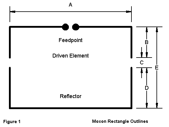
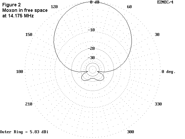
As a reference point, Figure 1 reviews the structure of a Moxon rectangle, while Figure 2 provides a free space pattern for a 20-meter Moxon rectangle. No dimensions are given here for the Moxon, but there are other notes at this site for wire Moxons from 10-40 meters. The sketch is from that note. Also note that the parts of the sketch with letter labels do not coincide with the parts of the Double D shown below.
The Double-D has a somewhat more complex geometry due to its elevated tails. Figure 3 illustrates the basic structure, with identification of the arms. The antenna forms a horizontal square, 28' from corner-to-corner for 20 meters. Dodd has preferred to make both Ds equal in overall length, although he reports one version with a very small difference in tail length between the driven element and the reflector.
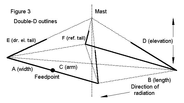
The best modeled performance I have been able to derive from a 20-meter version of the Double-D has required that the reflector tails be significantly longer than the driven element tails. Here are the dimensions of the best modeled version:
Table 1.  Dimensions for a bare-copper wire Double-D.

Designator     Item                     Length
A, B           Length/Width             19.8'
C              Arm length (from mast)   14.0'
D              Junction elevation        2.3'
E              Tail length, DE           7.9'
F              Tail length, Ref          8.2'

All element #14 copper wire.
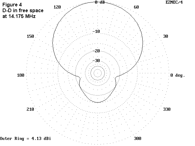
Notice that these dimensions use a very conservative elevation of the tails. More radical elevation changes, as well as shorter dimensions for the length and width, yield lower performance figures. Even so, the best free space gain obtained from the antenna has been about 4.1 dBi, with a front-to-back ratio just over 15 dB. As Figure 4 shows, the beamwidth is nearly 90 degrees, and the rear quadrant is well-behaved, that is, the rear quadrant shows a smooth pattern of rejection.
The Double-D is designed for compact yards or gardens and modest installations. The arms are nonconductors. The wires and cords from the arm ends to the mast serve double duty: as tails and as supports for the arm ends. A perimeter cord is recommended to keep the arms properly positioned laterally.
Over level average terrain, at a height of 1/2 wl (about 35' on 20 meters), the antenna exhibits a broad forward lobe and an equally broad rear lobe. The front-to-back ratio increases to about 22 dB, while the forward gain is in the neighborhood of 9.5 dBi. Figure 5 overlays a Moxon and a Double-D pattern for relevant comparison.
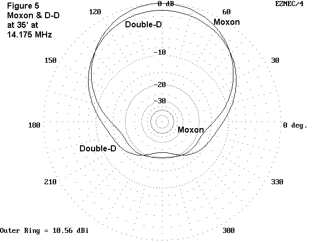
Although the two patterns look similar, there is a major difference: the elevation angle of maximum radiation for the Moxon is 26°, while the Double-D's take-off angle is 4° higher. The double-D falls considerably short of Moxon rectangle performance. However, it lends itself to somewhat easier construction, especially if one contemplates rotating the antenna by hand or rotor. For some types of operation, the front-to-back ratio may be of more utility than raw forward gain. A convenience is the fact that the feedpoint impedance is in the neighborhood of 50-55 ohms, a good match for coaxial feed systems.
In the end, however, Dodd's claims of 3-4 dB gain over a dipole do not fully materialize. At best, I have been able to model about 2 dB over a similarly situated dipole, and my models have been optimized. The end result is an antenna with somewhat less gain than a properly tuned X-beam, but with a superior rear pattern. It also has less gain than a 2-element Yagi shortened to about 2/3rds full size using linear or inductive loading at the feedpoint, although shortened Yagis are capable of quite good front- to-back ratios. These comparisons are intended neither to compliment nor condemn the Double-D, but only to place it relevantly within the cluster of antennas to which it belongs.
The dimensions have been altered by Dodd for the 2nd Edition of his excellent book, The Antenna Experimenter's Guide (RSGB), with some improvements in performance. However, compared to a standard Moxon Rectangle, which takes up very little more room for any given band, the high performance region occurs over a very narrow portion of the band. The newer version has a peak gain a little more than 3 dB better than a dipole. Because Peter's book is such a good reference volume for the antenna experimenter, I shall leave further details of the improvements "as an exercise for the reader."
Updated 3-18-97, 5-4-99. © L. B. Cebik, W4RNL. Data may be used for personal purposes, but may not be reproduced for publication in print or any other medium without permission of the author.