


|
|
 |
 |
 |
|
|

Antentop is FREE e-magazine devoted to Antennas and Amateur Radio an
Special page devoted to
The Helical Whip for RV and Mobile Use

Custom Search
|
ANTENTOP-
01- 2020, # 024
|
The
Helical Whip for RV and Mobile Use |
|
|
|
|
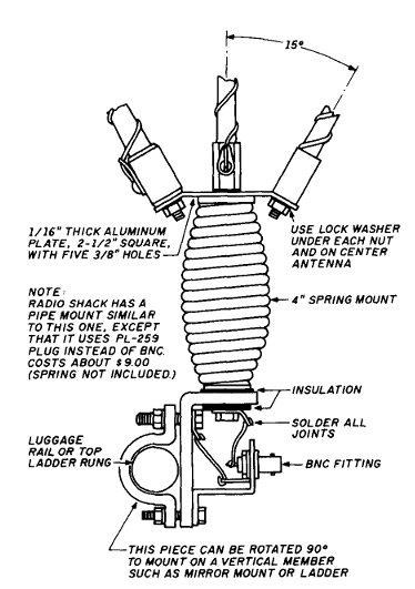
When attached to the common spring mount on the
top of the motor home, four of the antennas had low VSWR (less
than 1.5:1) without retuning. The center unit (20 meters) was affected slightly,
and I needed to shorten the tip ½ inch
to obtain the best VSWR for the phone band. The 20 meter antenna
also had narrow bandwidth, although it still covered the phone
band. For this reason, it might be better to put one of the narrow
band antenna (12 or 17 meters) in the
center. While traveling, tilting the assembly about 45 degrees
or more to the rear should help you avoid losing some of it to
an underpass or bridge. You will encounter another hazard in residential
areas, where large trees often overhang the streets. Mobile operation
is still quite feasible, even at a 45 degree tilt, if you mount
the assembly on a rear luggage rail or ladder. Testing Procedure I used the test setup in Figure 2 to check all the antennas
during construction. If you do not plan to go into heavy production,
the steel top of a car or pick up truc
should work quite well as a base for the magnet mount. Take precautions
to protect the top of the vehicle. A thin sheet of plastic should
work, as capacitance between the magnet mount and car top will
serve as an effective RF ground connection. I consider a grid- dip meter a must for checking
antenna resonant frequency, but an RX noise bridge may work if
you are proficient in its use. Checking VSWR is useless for initial
testing unless the resonant frequency happens to be in or very
near the band in question. If you have a BNC fitting in the magnet
mount, you can easily attach a small loop for grid- dip meter
readings, exchanging it for coax for testing VSWR or on- the-
air use. After you adjust an antenna roughly to the correct
frequency with the grid- dip meter, make the adjustments by connecting
the antenna to a transceiver and finding the frequency of lowest
VSWR with a VSWR meter. An adjustments
of as little ¼ inch to the tip of the antenna may be necessary
to bring lowest VSWR point to the center of the desired band. |
Figure 1 It is usually sufficient to check the VSWR every
100 kHz to find the low point. A dual needle VSWR meter is a real
time saver here. It is better to start with an antenna that is too
long; you can find the correct length with careful plunging. If
you have not found a low VSWR point after your first check with
a grid- dip meter, recheck the meter frequency. Don not be
concerned with other higher frequency dips. Some may be harmonic
dips and some may not. Depending on the length of the wire up
the point, the loading coil may act as a trap or a choke, creating
a much higher frequency dip. Construction
of the Modified CB Antenna The modified CB antenna
requires the least work and is very efficient. I recommend using
a top- loaded type with short tuning stubs at the very top, just
above the loading coil. The one I used had about 3 feet of helical
winding spaced evenly on constant diameter fiber glass rod, |
|
|
Page- 45 |
 |
 |
|
 |
|
|
|||
Just for Fun:

Powered byIP2Location.com
Thanks for your time!
Last Updated:
January 30, 2021 18:59