
|
|
 |
 |
 |
|
|

Antentop is FREE e-magazine devoted to Antennas and Amateur Radio an
Special page devoted to
VHF ATU

Custom Search
|
ANTENTOP- 01- 2017 # 021 |
Several Universal ATUs for the Whole Amateur HF Band
|
|
|
|
|
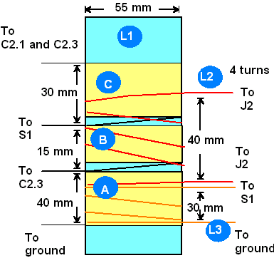
The coil has 3 turns of strand wire with a diameter
of 1.5 mm (#17 AWG). It is wound above coil L1 as shown in Figure 6. In the range of 18-32 MHz, the coupling
coil L3 allowed tuning of the SWR down to 1.2:1 with lots of my
experimental antennas. The ATU shown in Fig.
5 is a true simple and effective universal ATU. It has
only one switch, S1 that could be a simple toggle switch at power
up to 100 W and three variable capacitors with clear tuning. |
Figure 6
Placement of L3 |
|
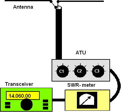
It is a bit easy to check the matching antenna that
is fed through a two wires open line.
Figure 7 System Transmitter- SWR Meter- ATU- Antenna |
Spacing should be no less than 0.5 mm for 50 watts
going to the ATU. If they do break down on transmission, it may
be necessary to avoid tuning the capacitors to total resonance.
However, this will reduce the effectiveness of the ATU. It is also
necessary to use high-quality variable capacitors with good contacts
on the rotor. This is important to the usage of the ATU on the upper
amateur HF ranges. An air variable high-voltage capacitor, C2, may
be used with the capacity range of 10 to 200 pF for the ATU. It
allows the reduction of the dimensions when the ATU is constructed.
In this case it becomes necessary to use a two-pole three-position
switch instead of the S1 toggle switch. The schematic for this ATU
is shown in Figure 9. In this ATU the C4 and C5 should be
selected for operation in the ranges of 3.5-1.9 MHz.
For 5 MHz band should be added additional pole on the switch.
Figure 8 Adjusting the universal ATU with Antenna
Feeding through Two Wires Line |
|
|
|
|
|
Page- 68 |

 |
 |
|
 |
Just for Fun:

Powered byIP2Location.com
Thanks for your time!
Last Updated:
February 26, 2018 21:43