
Antentop is FREE e-magazine devoted to Antennas and Amateur Radio an
Special page devoted to
VHF ATU

Custom Search
|
ANTENTOP- 01- 2017 # 021 |
Several Universal ATUs for the Whole Amateur HF Band |
|
|
|
|
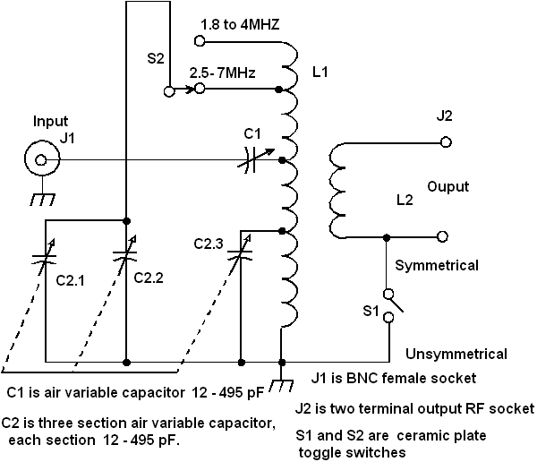
Figure 2 Universal ATU Covers 5- MHz Band |
|
|
|
|
|
The effectiveness of this ATU mostly depends on the quality of parts
and proper design. This is a resonant ATU and, therefore, on coil
L1 and capacitor C2 there is a high RF voltage during the transmission
time. These components must be of a high quality due to the high
voltage present otherwise you have got burnet stuff inside ATU
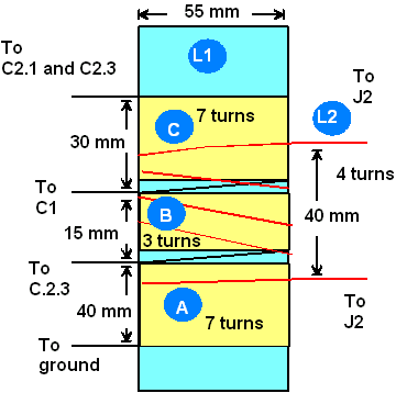
box... The coil L1 is wound on a form with an OD of 55 mm.
Each winding consists of: 1. Section A: 7 turns covering 40 mm length section
of the coil form 2. Section B: 3 turns covering 15 mm length section
of the coil form 3. Section C: 7 turns covering 30 mm length section
of the coil form |
Fig. 3 Design of L1 and L2 |
|
The coil form must be of a high quality material, RF
ceramic will do the job. The wire used for L1 should be no less
than 1-mm diameter (#18 AWG). The winding L2 is four turns and
it is wound in the middle part of L1 and covers 40 mm. L2 can
be wound using either stranded wire or solid wire with a diameter
of 1.5-2 mm (#17-#12 AWG). Insulation tape with high- voltage
capability should be used between L1 and L2.
Figure 3 shows design of the coils. |
Next step to improve the ATU was my attempt to build an ATU that could match load
(in this case antenna) with reactive component, particularly if
the reactive component was no more the value of the active component
of the load. C3 was added to this ATU to compensate the reactive
component of the load (antenna). The diagram of this modified
ATU is shown in Figure 4.
For the entire frequency Band from 1.8 to 32 MHz, the addition
of C3 allows the SWR to be no worse than 1.5:1 with an antenna
having such above mentioned reactive component. SWR of 1.2:1 in
the HF Band from 1.8-7 MHz can be achieved if antenna has any
resistive component of 20-300 ohms and has no reactance or little
one. |
|
|
|
|
Page- 66 |
|
 |
 |
|
 |
Just for Fun:

Powered byIP2Location.com
Thanks for your time!
Last Updated:
January 4, 2020 14:31


