
|
|
 |
 |
 |
|
|

Antentop is FREE e-magazine devoted to Antennas and Amateur Radio an
Special page devoted to
The GRASSWIRE:
Another Approach to Hidden HF Antennas

Custom Search
|
ANTENTOP- 01- 2017 # 021 |
The GRASSWIRE: |
|
|
|
|
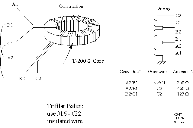
Figure
4 Balun for Grasswire Antenna |
|
|
|
|
|
How much wire? A general rule of
random wire antennas is to get as much wire in the air as you
can - longer is better. Does this still hold for the Grasswire? The answer is no. Measurements show that anything
over a wavelength does no appreciable good. My first measurement
program parked a car on a dirt trail, with a spool of 18 gauge
insulated wire unwound, one end tied to the bumper and the rest
run on down the trail. The dirt was average stuff, mostly clay
and loam on top of granite. At the car the wire was untied from
the bumper, passed through a small RF toroid, and connected to
an antenna tuner, the latter driven by a TR7 transceiver at approximately
fifty watts. The car itself served as a counterpoise. A ten-turn secondary
winding on the toroid drove a small diode and capacitor. RF current
in the antenna developed a DC voltage across the capacitor that
I measured with a handheld DC voltmeter. As the toroid slid along
the wire, the voltage dropped and fell below 10 percent of the
starting value a wavelength along the wire. |
There was a small
rise in voltage for a short bit farther along the wire, but at
a full wavelength it fell below one percent, and never showed
any further improvement. This measurement indicated
that the current in the wire dropped almost exponentially along
the wire, and beyond a wavelength was more than 20 dB down, so
could produce little radiation. The excess wire can simply be
removed. Thereafter my Grasswire deployments always used about one wavelength of
wire at the lowest operating frequency. Continuing the measurement
at a later date, an assistant and I laid a center-fed wire dipole
on a grassy field, 396 feet of insulated, 12 gauge wire - all
that we happened to have handy. Again a small toroid RF transformer
and diode/capacitor, similar to the earlier one, had one side
of the dipole threaded through it. A fiberglass surveyor's tape
stretched from the center along the dipole to one of its ends.
The DC voltage, measured as a function of distance along the wire
is a measure of the RF current. Figure 5 and Figure 6 show the
falloff of current along the wire at 7 and 29 MHz amateur Bands
and its attenuation by at least 20 dB at one wavelength (seventy,
and sixteen and a half feet, respectively.) |
|
|
|
|
|
Page- 34 |
 |
 |
|
 |
Just for Fun:

Powered byIP2Location.com
Thanks for your time!
Last Updated:
January 4, 2020 13:43