
Antentop is FREE e-magazine devoted to Antennas and Amateur Radio an
Special page devoted to
The GRASSWIRE:
Another Approach to Hidden HF Antennas

Custom Search
|
ANTENTOP- 01- 2017 # 021 |
The GRASSWIRE: |
|
|
|
|
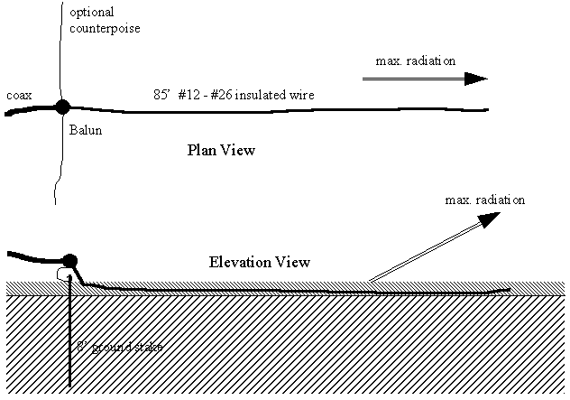
Figure
1 Plan
and Elevation views of a Typical Installation of Grasswire
Antenna |
|
|
|
|
|
The
grasswire radiates vertically polarized off the end
of the wire. Extensive monitoring tests with wires laid along
the great circle route toward WWV, and perpendicular to that line,
demonstrate the end-fire nature of the antenna. So why does it
work? When
a plane wave reflects from an air-earth boundary, an incoming
ray reflects, giving an outgoing ray. These two, and the line
normal to the boundary plane, form a plane of incidence.
Solutions of Maxwell's equations differ for the case of the E-field
being perpendicular to this plane (i.e., horizontally polarized),
and the case when the E-field vector is in the plane of
incidence. You
will probably call the latter "vertical" polarization,
although this is technically not correct. Electromagneticists
(a.k.a those who practice Electromagical
effects) refer to these cases as normal incidence (horizontal
polarization) and planar incidence (vertical polarization.) |
For
the normal incidence case, reflection is nearly total, with a
nearly 180 degree phase reversal. Thus very low antennas neither
respond to, nor generate, appreciable amounts of horizontally
polarized radiation. But for the planar incidence case, the reflection
varies in strength considerably. At some takeoff angle (angle between outgoing ray and
the ground) the reflection becomes quite weak, and has a 90 degree
phase shift. Near this angle, the sum of direct and reflected
rays will have a magnitude as if the antenna were in free space!
Of course, at other angles, ground reflection largely cancels
the direct ray, and the antenna does not radiate well at all. A
reflection coefficient is calculated as the ratio of the
electric field in the incoming ray to the electric field in the
reflected ray. It varies from one (total reflection without loss)
to zero (no reflection at all.) It depends on the takeoff angle,
frequency, and the soil parameters (dielectric constant and conductivity.)
Figure 2 shows plot of planar incident (vertical
polarization) reflection for typical "good"soils and
Figure 3
shows plot of planar incident (vertical polarization) reflection
for typical "poor"soils. |
|
|
|
|
Page- 31 |
|
 |
 |
|
 |
Just for Fun:

Powered byIP2Location.com
Thanks for your time!
Last Updated:
January 4, 2020 13:28


