
Antentop is FREE e-magazine devoted to Antennas and Amateur Radio an
Special page devoted to
The Three L-Antennas

Custom Search
|
ANTENTOP-
01- 2017, # 021 |
The Three L-Antennas |
||
|
|
|
||
|
It has
another notable feature. It develops a horizontal component from
the side arm. This gives some directionality and gain over a simple
vertical antenna. The directionality is a bit more broadside to
the side arm but generally semi-circular as seen in Figure 5.
The angle of the side arm can be used for tuning using ratios
as tall as a 3/4 up-bend . Ratio and arm angle influence the direction
of maximum gain. |
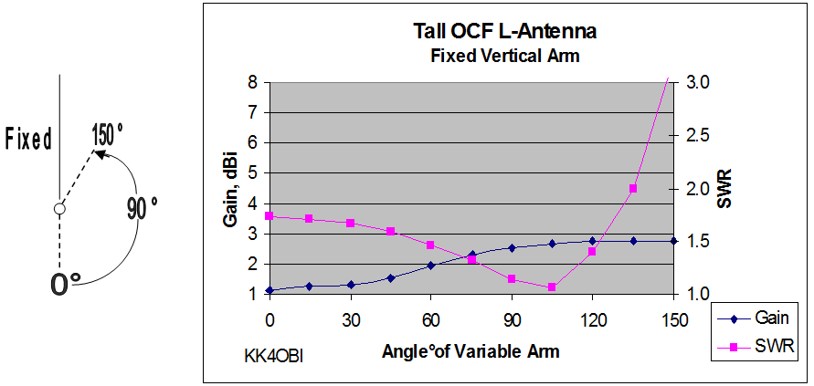
Using that
capability, Figure 4 below shows what happens to a Tall OCF
dipole as the shorter lower arm is swung upwards in 15 degree increments from 0
degree (down), to 90 degree (horizontal), to 150 degree (60 degree
up).
|
||
|
|
|||
|
|
|
||
-------------------------------------------------------- |
|||
|
|
|||
|
Model Example (Figure 5) Conditions:
4NEC2 software (Reference 10) model of a Tall-L Antenna, fed at
½ wavelength over real ground using #14 wire, optimized at 28.4 MHz. Predicted
dimensions: Vertical arm: 3.147 meters tall; Horizontal arm: 2.08
meters long. Total
length: 5.227 meters at 60-40 ratio. Impedance:
50.5- j0.43; SWR:
1.01; Gain: 2.69 dBi At page
16 is the 3D view and horizontal/vertical polar
graph produced by the model. |
Note: the radiation pattern is 2.69 dBi on the hemisphere towards the side arm. The opposite
side has 0.01 dBi gain therefore signals
are about half as loud from the back hemisphere. Compare this
with an omni-directional 1.5 dBi circle
which is the norm for a vertical antenna. Observe the 10-degree low
angle radiation for DX and the stronger signal at a 40-degree
upward angle. No energy is wasted skyward. |
||
|
|
|
||
|
Page-15 |
|||
 |
 |
|
 |
Just for Fun:

Powered byIP2Location.com
Thanks for your time!
Last Updated:
January 3, 2020 22:48


