

Antentop is FREE e-magazine devoted to Antennas and Amateur Radio an
Special page devoted to
MEMORANDUM ON THE BEVERAGE WAVE ANTENNA
FOR RECEPTION OF FREQUENCIES IN THE
550 - 1500 KILOCYCLE BAND

Custom Search
|
ANTENTOP- 01- 2016 # 020 |
Memorandum on the Beverage Wave
Antenna |
|
|
|
|
practically no effect on signals arriving in phase at A from
B direction. Therefore it is necessary to know the surge
impedance of the two wires in parallel with respect to ground. The transformer Tr reverses the phase and sends
the signal which arrives from A direction back over the two-wire
line |
now acting only as a transmission line. The primary coil is designated
to match the surge impedance of the two-conductor antenna line
in parallel with respect to ground and the secondary to match
the same two-conductor antenna as a transmission line back to
the station. |
|
|
|
|
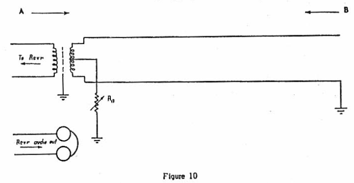
Circuit
for Determining Surge Impedance Forward Reception
|
|
|
A signal is tuned
in from A direction on the receiver. Frequencies of multiples
of one-half wave length are preferred as the are more completely balanced out when the proper resistance
value is used at Rb. The resistance
Rb is adjusted for minimum signal in
the phones and this value used as the antenna surge impedance.
The surge impedance may also be determined by adjusting the resistance
at the opposite end of the antenna. In this
case signals from B direction are tuned in to the receiver and
balanced out by varying Ra. This method will usually give
a lower value of Ra than that recorded for Rb
in the other case. The difference is due to the R.F. resistance
of the primary of the transformer and some residual inductive
reactance, as unity coupling between turns is not possible.
If the recorded value of resistance is low it is an indication
of high ground resistance. |
Values
at Grand Island for two wires in parallel are approximately 300 ohms. Another
and more simple method which has been employed is to make the
resistance Ra, Rb variable in steps of 20 ohms from 230-440 ohms.
With an observer at the receiver, the readings are recorded as
changed at the antenna terminal and as indicated on a meter in
the second detector plate circuit of the receiver for each changed
step of the resistance. The observer at the receiver hears
a click when the resistance is switched to the next step.
Its value is known according to a shifting plan as prearranged
with the antenna terminal collaborator and the proper impedance
value thus determined. |
|
Circuit for Determining Surge Impedance
Rear Reception
|
|
|
Page- 90 |
|
 |
 |
|
 |
Just for Fun:

Powered byIP2Location.com
Thanks for your time!
Last Updated:
February 23, 2018 23:36


