


|
|
 |
 |
 |
|
|
Antentop is FREE e-magazine devoted to Antennas and Amateur Radio an
Special page devoted to
Simple HF Regenerative Receiver

Custom Search
|
ANTENTOP- 01- 2013 # 017 |
Simple HF Regenerative Receiver |
||||||||||||||||||||||||||||||||||||||||||||||||||
|
|
|
||||||||||||||||||||||||||||||||||||||||||||||||||
|
Figure 1 shows the schematic
of the receiver. Points 1 and 2 are
heater. Point 3 is ground (minus) and point 4 is plus of the plate
voltage. The receiver works fine from 100- 250- V. Table 1 shows data for capacitors
and resistors. Inductors of the receiver are coiled on the base
from old tubes. Figure
2 shows design of the coil. Distance between inductor
L1 and L2 shown approximately. The distance may vary when it would
be tuned on to smooth regeneration of the receiver. Table 2 shows data for the inductor. Analog the
Russian Pentode is: to firs tube is: 6J7, Z63, 6W7, EF36, EF37A. Analog for Russian
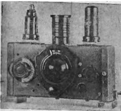
twin Triode is: 6N7GT. Also may be used: B65, ECC32, 6CC10, 6SN7GT. Receiver built on aluminum L- shape profile. Figure 3 shows view of the receiver. Tubes and
Plug- In Inductor placed at the upper side of the receiver. Figure 4 shows inside view on to the design.
All connections made by stranded wire in diameter of 1.0- mm (18-
AWG). |
Radio # 3, 1946 |
||||||||||||||||||||||||||||||||||||||||||||||||||
|
Table
1 Data
for capacitors and resistors
|
|||||||||||||||||||||||||||||||||||||||||||||||||||
|
Figure 2 Design of the Plug- In Coil |
Figure 3 Regenerative Receiver |
||||||||||||||||||||||||||||||||||||||||||||||||||
|
|
|
||||||||||||||||||||||||||||||||||||||||||||||||||
|
|
Page- 81 |
||||||||||||||||||||||||||||||||||||||||||||||||||

 |
 |
|
 |
Just for Fun:

Powered byIP2Location.com
Thanks for your time!
Last Updated:
January 9, 2020 22:40