


|
|
 |
 |
 |
|
|
Antentop is FREE e-magazine devoted to Antennas and Amateur Radio an
Special page devoted to
Pencil Tubes

Custom Search
|
ANTENTOP- 01- 2012, # 016 |
Pencil Tubes |
|
||||
|
|
|
|
||||
|
Mixer Mixer on the pencil tubes may be made on one- grid or two grid schematic.
At the one- grid schematic both input RF signal and RF- voltage
from a heterodyne oscillator come on to the first grid of the
tube. Voltage from a heterodyne oscillator should not be exceed
1.5- 2.0- V or side channels may be appeared. Two- grid mixer
works more stable the one- grid one. Figure
2 shows a typical schematic of a two- grid mixer on
a pencil tube. Input RF- voltage goes to the first grid and Voltage
from a heterodyne oscillator goes to the third grid. Voltage from
a heterodyne oscillator should not be less the 12- 15- V. Practically
any pencil tubes may work like a mixer. Such mixers- one and two-
grid, may work up to VHF- Frequencies. |
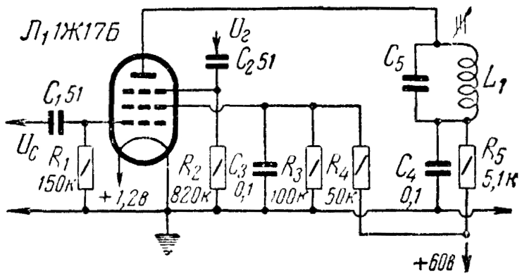 Figure 2 Two- Grid Mixer on a Pencil
Tube |
|
||||
|
IF amplifier IF amplifier made on the pencil tubes may include 3 or 4 the same stage.
Figure
3 shows one of the stages. IF amplifier made on the
pencil tubes may work on frequencies from hundreds kHz up to several
tens MHz. |
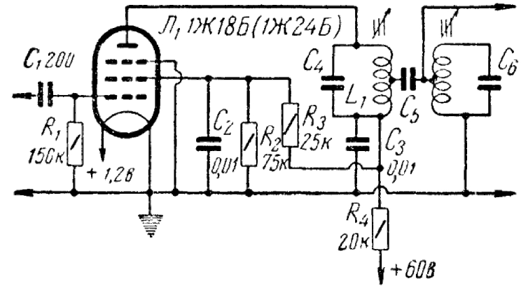 Figure 3 One Stage of a multistage
IF amplifier |
|
||||
|
RF Oscillator Pencil tubes may work at any common schematic of the RF- oscillator where
usual tubes are used. Practically any type of pencil tubes may
work in RF Oscillator. As usual a Colpitts oscillator is used at the
VHF- band for producing RF- Frequencies up to 300- MHz.
Figure
4 shows Typical Schematic of a Colpitts
Oscillator. For stable work the tank L1C1 is tuned to the frequency
twice below that LkC8 is tuned. |
 Figure 4 Typical Schematic of a
Colpitts Oscillator on a Pencil Tube |
|
||||
|
|
|
|||||
|
|
Page- 90
|
|
||||

 |
 |
 |
 |
Just for Fun:

Powered byIP2Location.com
Thanks for your time!
Last Updated:
January 19, 2020 13:59