


|
|
 |
 |
 |
|
|
Antentop is FREE e-magazine devoted to Antennas and Amateur Radio an
Special page devoted to
EH Antenna for the 20- meter Band

Custom Search
|
ANTENTOP- 01- 2012, # 016 |
EH Antenna for
the 20- meter Band |
|
|
|
|
|
|
Next step is to connect
the antenna parts between each other. The stage requires patient
and attention. At first, connect by wire in plastic insulation the upper
end of the lower cylinder with lower end of the tuning inductor.
(See Figure 1) For this connection do
holes in dia 2- mm near the upper end of the lower cylinder and
lower end of the tuning inductor. Take the length of wire that
a little more the distance between the holes. The wire should
go inside the tube and the wire should touch by all it length
the inner surface of the tube. Tin ends of the wire. Bend the tinned ends of the wire onto 90- degree.
Then insert the tinned ends of the wire into holes. Use all tools
that you can find or make. I personally used a wood stick with
a slot. An end of the wire was inserted to the slot then the end
was inserted into the hole. After that the end was bended and
soldered to the cylinder. Then next end of the wire was inserted
into the hole and straight away bended and soldered to the tuning
inductor. |
At second, connect by wire in plastic
insulation the lower end of the phase inductor with upper end
of the tuning inductor. (See Figure 1) Preliminary do the same things as was done with the first wire. However the wire should go into center of the tube.
You
may use some kind of spreader to keep the distance equal inside
the tube. Figure 8 shows the wires inside
of the tube. At third, last step to make the EH-
Antenna. Install the cap with an RF- socket and an input inductor.
Figure 9 shows the cap. Do holes
for fastened RF- Socket by screw with nuts and install this one. Figure 10 shows the cap with the RF-
Socket. Cut half part of plastic from the cap, install wires and
input inductor. Figure 11 shows the cap with the
RF- Socket and the input inductor. Well, do not hurry to install
the input inductor it should be installed after a preliminarily
tuning of the antenna. The inductor helps get the minimum SWR
in the antenna. Tuning inductor may contain 5- 7 turns. Diameter
of the inductor is 12- 15- mm. It made by wire in plastic insulation
(similar wire that was used for the phase inductor). The inductor must be placed perpendicularly to axis
of the plastic tube. |
|
 Figure 8 Wires inside of the Tube |
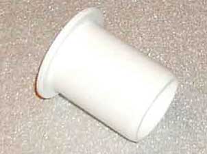 Figure 9 Tube Cap |
|
|
Figure 10 Tube Cap with RF- Socket |
|
|
|
|
Page-50
|
|
 |
 |
 |
 |
Just for Fun:

Powered byIP2Location.com
Thanks for your time!
Last Updated:
January 19, 2020 12:56