
Antentop is FREE e-magazine devoted to Antennas and Amateur Radio an
Special page devoted to
Grounded
and Underground Antennas

Custom Search
|
ANTENTOP- 02- 2010, # 014 |
Grounded and Underground Antennas |
|
|
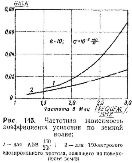
Figure 145 Experimental
data of the (antenna) gain Vs frequency by the ground wave: 1. Travelled
Wave Antenna- 150 meter
length of wire hanged at 2.8-meteres above the ground 2. Grounded
(sitting on the ground) Insulated Wire in 150- meter length |
||
|
Underground antennas are more long life compare to
TWA and Ground Antennas. Underground antennas can work because
horizontal component of the EMF (Electromagnetic Field) can penetrate
into the ground (Figure 131).
So, as a rule a horizontal wires used for underground antennas.
Efficiency of the underground antennas is depended
onto parameters of the soil. Antennas placed into wet soil have
gain less compare to antennas placed into dry soil. The decreasing of the antenna gain of the underground
antenna in the wet soil can be explained by increasing of the
attenuation of the radio- wave in the antenna wire (but not the
attenuation of the radio- wave in the wet ground). |
(Note from I.G.:I had several pieces of the antenna wire from the underground
antennas. It was copper wire inside the round (16-mm OD) white
thick plastic shield. A strong black plastic (thickness near 1-mm)
was above the white plastic shield) or installed the
antenna in the underground cavities or trench (Trench Antenna).
Often an usual coaxial cable
is used for installing the Cable Underground Antenna. Figure 146
shows real design of the Cable Underground Antenna. The antenna is made from a length of 15-meters of a
Russian coaxial cable RK-3 (or RK-6). Table 1 shows data for some old- age Russian
Coaxial Cables. Copper braid is removed at the length of 10 meters
(part 1 of the antenna). Antenna is dug in a trench onto depth
of 0.2- 0.5- meters. Antenna is located to the needed direction. Part 2
of the antenna is the feeder. The feeder is going to bunker 3
where a transmitter is installed. Part 4 shows terminal for connection
with a transmitter. |
|
|
Page-17 |
||
 |
 |
 |
 |
Just for Fun:

Powered byIP2Location.com
Thanks for your time!
Last Updated:
January 19, 2020 21:09


