


|
|
 |
 |
 |
|
|
Antentop is FREE e-magazine devoted to Antennas and Amateur Radio an
Special page devoted to
Some Thoughts on Regenerative Receivers

Custom Search
|
ANTENTOP- 01- 2010, # 012 |
Some Thoughts on Regenerative Receivers |
|
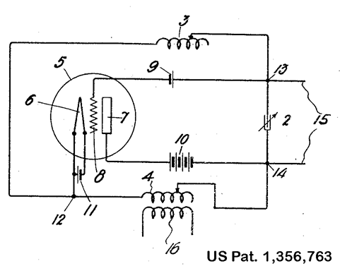
Note from Wiki: The Hartley oscillator was
invented by Ralph V. L. Hartley while he was working for the Research
Laboratory of the Western Electric Company. Hartley invented and
patented the design in 1915 while overseeing
Figure Credit Line: Wiki |
|
|
3. Smooth regeneration. This is the hard nut to crack.
There is no really good answer here, in my opinion. This
, plus the interaction problem was one of the major reasons
for the decline in popularity of the regenerative receiver, as
well as reduced component costs which made superhetrodyne receivers
practical. However, a well regulated power supply to the regeneration
stage helps a great deal. A Zener or comparable regulator in transistor
circuits, or gas discharge tube for vacuum tubes will work well.
I note that one commercial regenerative receiver simply uses a
separate 9 volt battery for the detector, and a second for the
audio amplifier. Now, keeping in mind the "simplicity" issue,
we can see where these fit into our design process. The decoupling of the tuned circuit from the antenna
serves two purposes. First, it reduces the interaction of your
antenna with the detector tuned circuit. If you have ever hooked
an antenna analyzer to a random wire antenna, the impedance is
all over the place. Investment in a good antenna tuner, such as
the MFJ-16010 is money well spent. Of course, a home-brewed tuner
is also feasible, either built-in to the receiver, or as a separate
unit. Any of the the "QRP" designs will do the trick.
The coupling of a resonant antenna into the detector can often
lead to "dead" spots in tuning. Hence, the advantage
of isolating the antenna from the detector with a "front
end." |
There is no need to have this front end tuned, but just to keep the antenna interactions from the detector,
and reduce or partially prevent radiation from the oscillating
detector from producing QRM for other radio users in the vicinity. When running in "oscillation" mode, or close
to it, a regenerative detector is its own little QRP transmitter!
For domestic and neighborhood tranquility, the isolation amplifier
greatly reduces radiation back into the antenna. It is not perfect,
and my two commercial kit regenerative receivers make an impromptu
signal generator in the ham shack when needed. An "RF"
gain control can be easily introduced to reduce the strength of
incoming strong signals, such as some of the major SW stations,
like Radio Havana, or the PRC stations. Along with the simplicity issue, the design for convenient
band switching of the detector's tuned circuit is a hassle. If
the "tickler" design of the classic Armstrong set is
used, then there are either two or three coils that have to be
switched. This means at least a three-pole n-throw switch if there
is a "primary" coil to the antenna. Three of the six
coil points are "ground" for RF, so only a three pole
switch is needed. If a coupling adjustment capacitor is placed
on the primary side to ground, then at least four points are "hot"
for RF. These switches are not only complex, but they are expensive
and add a large measure of complexity and increased size to the
receiver. There are at least two common alternative solutions: |
|
|
Page 66 |
63 64 65 66 67 68 69 70 101 102
 |
 |
 |
 |
Just for Fun:

Powered byIP2Location.com
Thanks for your time!
Last Updated:
January 22, 2020 21:49