


|
|
 |
 |
 |
|
|
Antentop is FREE e-magazine devoted to Antennas and Amateur Radio an
Special page devoted to
Directional
Helical Antennas

Custom Search
|
ANTENTOP- 01- 2010, # 012 |
Directional Helical Antennas |
||||||||||||||||
|
|
|
||||||||||||||||
|
Table 1 Data for testing of the Helical Antenna
|
|||||||||||||||||
|
|
|
||||||||||||||||
Column "S- Meter"
shows normalized level- Helical Antenna/WINDOM. For example, digit
"2" shows that level from the Helical Antenna is in
2 times more (according to the S- meter of the receiver) compare
the level from the WINDOM
|
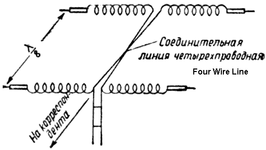
Figure
5 shows the design of the Four- Wire Line. The Four-
Wire Line was placed onto insulators under the square wood stick.
The Small Directional Dipole Helical The small sized Antenna at
the test showed that this one worked similar to the helical antenna
shown on the Figure 1.
|
||||||||||||||||
|
It was tested Directional Dipole Helical Antenna with
reduced sizes. Length between the Helical Dipoles was lambda/8,
or 2.6-m for the 20- Meters Band. However there was used Four-
Wire Open Line between the Dipoles. Figure 4
shows the design of the Small Directional Dipole Helical Antenna. |
However, the Small Directional Dipole Helical Antenna
was more complicated in the tuning compare to Antenna from the
Figure 1.
The antennas were fed by 500- Ohm two- wire line with length 15.6-m
(3/4- Lambda). |
||||||||||||||||
|
Figure
4 Design of the Small Directional Dipole Helical Antenna |
|||||||||||||||||
|
The antennas were fed by 500- Ohm two- wire line with
length 15.6-m (3/4- Lambda). Tuning of the Directional Dipole Helical Antenna (for both antennas- Figure 1
and Figure
4): |
2. TX is tuned to the middle of the 20- meter Band and
its PA is tuned to the resonant with the line. |
||||||||||||||||
|
|
|
||||||||||||||||
|
|
|||||||||||||||||
|
|
|
||||||||||||||||
|
|
Page-36 |
||||||||||||||||
 |
 |
 |
 |
Just for Fun:

Powered byIP2Location.com
Thanks for your time!
Last Updated:
January 21, 2020 22:28