


|
|
 |
 |
 |
|
|
Antentop is FREE e-magazine devoted to Antennas and Amateur Radio an
Special page devoted to
Directional
Helical Antennas

Custom Search
|
ANTENTOP- 01- 2010, # 012 |
Directional Helical Antennas |
|
|
|
||
|
|
|
|
|
|
I..Kapustin, UA0RW Radio # 7 1958, pp.: 34-35. |
|
|
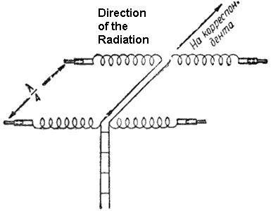
The antenna intended for the 20-meter Band. Figure 1
shows the design of the antenna. There are two Voltage Fed Helical
Dipoles that fed with phase shift in 90 degree. |
|
|
|
|
||
|
The distance between the Helical Dipoles is Lambda/4.
A Helical Dipole made of two plastic tubes in 3-cm diameter (it
is possible to use wood rectangular 3x3- cm) and 110-cm in length.
Two spirals in 77 turns of wire cord in 3-mm (9-AWG) diameter
are coiled above the each tube. Gap between near coils is 7.5-mm.
Ends of the dipoles (made from tubes) are plugged by wood. In
the plug a copper tube by length in 45-cm and 8-mm OD is inserted.
Antenna wires are soldered to the copper tube near the plug. Bare
wire (or tube) with OD that can fit inside the copper tube is
inserted into. Antenna is tuned into resonant by moving the bare
wire. Figure 2
shows the design of the tube ending. The Helical Dipoles are fastened to
a traverse made from a strong square wood stick. The stick is
fastened to an antenna mast. Open Wire Line made of copper cord
wire (3- mm (9-AWG) OD), the distance
between wires is 6-cm. The line is sitting on insulators under
the strong square stick. Length of the line is 5.2- m. Design
of the Directional Dipole Helical Antenna is shown on Figure 3. |
|
|
|
|
|
|
|
|
Page-34 |
|


 |
 |
 |
 |
Just for Fun:

Powered byIP2Location.com
Thanks for your time!
Last Updated:
January 21, 2020 22:23