


|
|
 |
 |
 |
|
|
Antentop is FREE e-magazine devoted to Antennas and Amateur Radio an
Special page devoted to
Atmospheric Current: Practical Experiments

Custom Search
|
ANTENTOP-
01- 2008, # 010 |
Atmospheric Current: Practical Experiments |
|
|
|
||
|
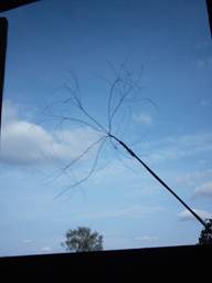
Other experiment I made in summer, in hot weather (+28
C) at weak wind. Broom was made from a steel wire rope. The rope
contained 49 steel wires, I untwisted
the rope in length near 20 centimeter.
Figure
1 "Broom- Rope Antenna." Figure
1 Broom- Rope Antenna from the untwisted rope Broom was fixed on the end of the 7-meter fishing tackle, end of this one was fixed to a dry pine pole. The
mast of 12 meters length was fixed to the bungalow, so the Broom
Antenna was at 9 meters over grounded metal roof. Figure 2 shows the design. A thin insulated wire was going from the Broom to the
"plus" of the multimeter, "minus"
of the multimeter was connected with the ground. A capacitor 4-mkFx250-V
having very low leaking was connected to bridge to the multimeter
probes. The capacitor shunts RF and filters fast fluctuation of
the antenna current. Now the antenna current was measured for
sure. The current was +0.15 nano-A at with some unexpectedly big
fluctuations. Several hours of measurement showed that max current
was several nano-A (Figure 3). Sometimes the current changed the polarity,
I observed minus 0.3 nano-A. The antenna current fluctuations
may be caused by wind that moves air areas with different volumetric
charge around Broom Antenna. |
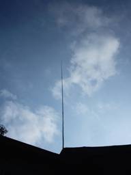
Figure
2 Broom Antenna in the night sky Conclusion 2:
Current from the Broom to the antenna wire is existed and prove
the "quite" discharge from ends of broom wires. The
current is very unstable by amplitude and may change polarity
at clear weather. Ever simple digital multimeter can measure the
current. There are no doubts that "quiet" discharge
has an area with a negative resistance. It is possible to find
lots data about it in the Internet. Figure
4 (taken from Reference 2) shows a Volt/ Ampere diagram of such
discharge. Almost the same diagram you may find at Reference 3. Take attention that at the left area there are nano-Ampere
current area. It is so-called "quite" or Townsend's
discharge. At right area (arc discharge) there are current at
several Amperes. Both areas have parts with a negative resistance.
Nano-area begins from current near 100- nano- Ampere. However
the current depends on lots conditions... My experimenters (made in 2000- 2001 years) proved
that discharge may began at relative
low voltage and enough large distance between electrodes (see
Reference
4). I did the experimenters at my table so I do
not know how discharge would be flow at a Broom Antenna. At the
experimenters I was observed relaxation oscillations. The oscillations
were detected by the help of oscilloscope. It may be detected
by ear like weak hissing. Townsend was observed this phenomenon
at 20- 30s of the 20- century. |
|
|
|
|
|
|
|
Page 23 |
|
 |
 |
 |
 |
Just for Fun:

Powered byIP2Location.com
Thanks for your time!
Last Updated:
February 2, 2020 22:22