

|
|
 |
 |
 |
|
|
Antentop is FREE e-magazine devoted to Antennas and Amateur Radio an
Special page devoted to
Field Antenna for the 40- meters

Custom Search
|
ANTENTOP- 01- 2006, # 008 |
Field Antenna for the 40- meters |
|
|
Figure 5 Base
of the antenna |
||
|
Note by VA3ZNW: MMANA does not provide correct simulation
when elements of the antenna aerial are located close to the ground.
NEC- 2 for MMANA should be used in the situation. So by me the antenna
was simulated in NEC- 2 for MMANA. Figure 7 shows the diagram directivity and data for the antenna.
Input impedance is near 21 Ohm, capacitor should be had 132-pF.
For matching the antenna with 50-Ohm coaxial cable an inductor
0.9 micro Henry should be turn on across antenna clips, and base
capacitor C should be used on to 100-pF. Off course, the real
capacity should be found at tuning of the antenna. Figure 8 shows the circuit of this matching device. Figure 9 shows parameters of the antenna depending on ground,
above which the antenna is located. As you can see, the ground
does not influence much to the parameters of the antenna. So,
the antenna can be placed above any ground. 11.
Average (Eps=13, Sigma=5) 12. Poor
(Eps=13, Sigma=2) 13. Pastoral
(Eps=13, Sigma=6) 14. Marshy
land (Eps=12, Sigma=7.5) 15. Pastoral
rich (Eps=14, Sigma=10) 16. Very good (Eps=20,
Sigma=30) |
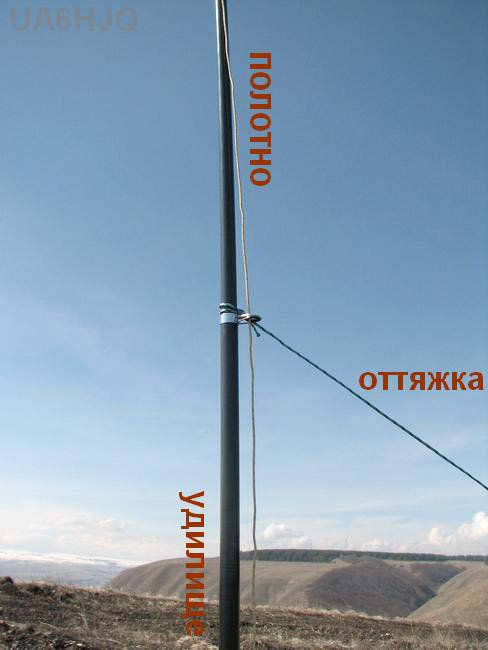
Figure 6 Wire and guys of the antenna at mast |
|
|
|
||
|
|
||
|
|
|
|

 |
 |
 |
 |
Just for Fun:

Powered byIP2Location.com
Thanks for your time!
Last Updated:
February 8, 2020 17:50